|
Читайте также: |
Note the directional arrow on the wheel
14.11a Install the axle bolt...
5 Remove the long wheel spacer from the
right-hand side of the wheel and the short
spacer from the left-hand side for safekeeping
(see illustration).
Caution: Don't lay the wheel down and allow it to rest on a disc - the disc could become warped. Set the wheel on wood blocks so the disc doesn't support the weight of the wheel.
|
| 14.11b... and tighten it to the specified torque |
6 Check the axle for straightness by rolling it on a flat surface such as a piece of plate glass (first wipe off all old grease and remove any corrosion using fine emery cloth). If the equipment is available, place the axle in V-blocks and measure the runout using a dial gauge. If the axle is bent or the runout exceeds the limit specified, renew it.
7 Refer to Section 16 if wheel bearing renewal is required.
Installation
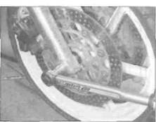
8 Apply a smear of grease to the inside of the wheel spacers, and also to the outside where they fit into the wheel. Fit the long spacer into the right-hand side of the wheel and the short spacer into the left-hand side (see illustration 14.5). Each side of the wheel can be identified using the directional arrow cast into one of the spokes near the rim (see illustration). The arrow denotes the normal direction of rotation of the wheel,
9 Manoeuvre the wheel into position, making sure the directional arrow is pointing in the normal direction of rotation. Apply a thin coat of grease to the axle.
10 Lift the wheel into place between the fork sliders, making sure the spacers remain in position. Slide the axle in from the left-hand side (see illustration 14.4b).
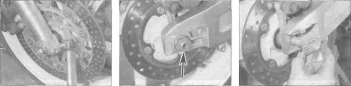
11 Install the axle bolt and tighten it to the torque setting specified at the beginning of the Chapter (see illustrations). Use a screwdriver inserted through the holes in the end of the axle to counter-hold it (see illustration 14.4a).
12 Tighten the axle clamp bolts on the bottom of each fork to the specified torque setting (see illustration).
13 Install the brake caliper, making sure the pads sit squarely on each side of the disc (see illustration 3.3b). Tighten the caliper mounting bolts to the specified torque setting (see illustration 3.17).
14 Apply the front brake a few times to bring
the pads back into contact with the discs. Move the motorcycle off its stand, apply the front brake and pump the front forks a few times to settle all components in position. 15 Check for correct operation of the front brake before riding the motorcycle.
15 Rear wheel -
removal and installation
Removal
1 Position the motorcycle on an auxiliary stand so that the wheel is off the ground. If required, remove the Icwer fairing so that the stand can be fitted (see Chapter 8).
2 Unscrew the axle nut, and on L. N and R models remove the ad|uster position marker from the end of the axle (see illustrations).
3 Support the wheel then withdraw the axle from the left-hand side and lower the wheel to the ground (see illustration 15.10a). On l_, N and R models retrieve the other adjustment position marker. On J and К models, the markers will probably stay on the ends of the swingarm, but they can be removed if required. Note how the caliper bracket locates against the swingarm, and support it so that it will not fall off. If required, displace the brake caliper bracket from the swingarm, noting how it fits, and tie it to the top of the frame, making sure no strain s placed on the hose (see illustration 15.7).
|
Дата добавления: 2015-10-29; просмотров: 163 | Нарушение авторских прав
| <== предыдущая страница | | | следующая страница ==> |
| Remove the split pin (A) and withdraw the clevis pin (B) | | | Tighten all the clamp bolts to the specified torque |