|
Читайте также: |
|
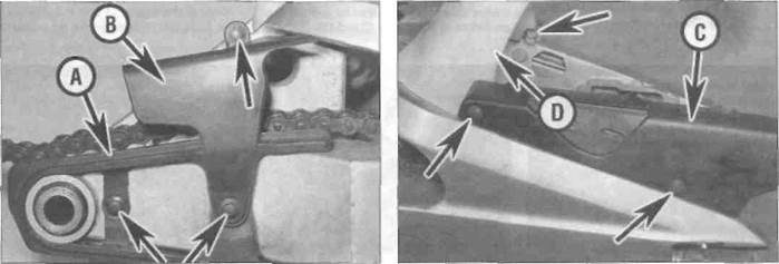
A Unscrew the bolts (arrowed) and remove the chain slider (A), the front chainguard (B),...
B... the rear chainguard (C) and the mudguard (D)
6*22 Frame, suspension and final drive

|
13.13a Thread in the adjuster bolt a couple of turns
13.13b Tighten the adjuster bolt as shown to the specified torque
chain slider is badly worn or damaged, it should be renewed. If required, split the drive chain at its joining link to separate the chain from the swingarm (see Section 15i. 10 If attached, and if required, separate the suspension linkage from the swingarm (see Section 11). Inspect all components for wear or damage as described in Section 14.
Installation
11 If removed, install the mudguard, chainguards and chain slider (see illustrations 13.9a and b).
12 Lubricate the dust seals, bearings, sleeve or collar, and the pivot bolt with grease.
13 If removed, thread the adjuster bolt a couple of turns only into the swir.garm (see
B... and tighten it as described,
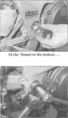
Using the special tool, to the specified
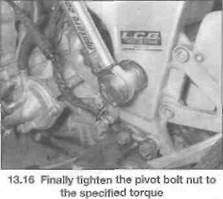
Torque
illustration). Offer up the swingarm and have an assistant hold it In place. Install the pivot bolt through the swingarm and engage its flats with those of the adjuster bolt (see illustration 13.8). Tighten the adjuster bolt to the torque setting specified at the beginning of the Chapter by turning the pivot bolt using a suitable Allen key (see illustration).
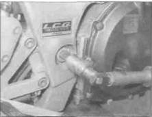
14 Thread the pivot bolt nut finger-tight onto the left-hand end of the bolt (see illustration).
15 Install the adjuster bolt locknut and tighten it as much as possible by hand (see illustration). Tighten the locknut further using the service tool as described in Step 6, and using an Allen key applied through its middle to counter-hold the pivot bolt and adjuster bolt and prevent them from turning. Then, using a torque wrench applied to the hole in the arm of the service tool, tighten the locknut to the specified torque setting (see illustration). Note: The specified torque setting takes into account the extra leverage provided by the service tool and cannot be duplicated without it.
16 Tighten the pivot bolt nut to the specified torque setting, again using an Allen key to counter-hold the pivot bolt and adjuster bolt and prevent them from turning (see illustration).
17 Install the rear shock absorber and linkage assembly as required by your removal procedure (see Sections 10 and 11).
18 Fit the drive chain around the front sprocket, then install the sprocket cover with its guide plate, making sure the speedometer cable drive socket on the inside of the cover engages correctly with the head of the sprocket bolt (see illustration 16.9). On L, N and R model, do not forget the wiring clip with the lower bolt. If removed, attach the speedometer cable to the drive housing. Install the gearchange linkage arm onto the end of the shaft, aligning the punch marks, and tighten the pinch bolt (see illustration 16.1a).
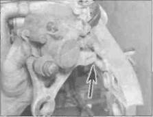
19 Locate the brake caliper bracket lug into the swingarm (see illustration) and attach the brake hose guide (see illustration 13.3).
20 install the rear wheal (see Chapter 7).
21 Check and adjust the drive chain slack (see Chapter 1). Check the operation of the rear suspension before taking the machine on the road.
14 Swingarm - inspection ^
and bearing renewal Sv
Inspection
|
| 13.19 Locate the lug on the bracket into the slot in the swingarm (arrowed) |
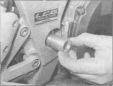
1 Remove the sleeve (J and К models) or collar (L, N, and R models) from the left-hand
Frame, suspension and final drive 6»23

14.1 Remove the sleeve or collar
side of the swingarm (see illustration). Lever out the seals from each side, taking care not to damage them.
2 Thoroughly clean all components, removing all traces of dirt, corrosion and grease.
3 Inspect all components closely, looking for obvious signs of wear such as heavy scoring, and cracks or distortion due to accident damage. Any damaged or worn component must be renewed.
4 Check the swingarm pivot bolt for straightness by rolling it on a fist surface such as a piece of plate glass (first wipe off all old grease and remove any corrosion using fine emery cloth). If the equipment is available, place the axle in V-blocks and measure the runout using a dial indicator. If the axle is bent or the runout excessive, renew it.
Дата добавления: 2015-10-29; просмотров: 152 | Нарушение авторских прав
| <== предыдущая страница | | | следующая страница ==> |
| Remove the cap to access the air valve | | | Bearing renewal |