|
Читайте также: |
bending up the remaining tabs to release it from the adjuster nut if necessary (see illustration). Inspect the tabs for cracks or signs of fatigue. If there are any, discard the lockwasher and use a new one; otherwise the old one can be reused.
4 Supporting the bottom yoke, unscrew the adjuster nut using either a C-spanner, a peg-spanner or a drift located in one of the notches, then remove the adjuster nut and the bearing cover from the steering stem (see illustration).
5 Gently lower the bottom yoke and steering stem out of the frame.
6 Remove the upper bearing and its inner race from the top of the steering head (see illustration). Remove all traces of old grease from the bearings and races and check them for wear or damage as described in Section 9. Note: Do not attempt to remove the races from the frame or the lower bearing from the steering stem unless they are to be renewed.
Installation
7 Smear a liberal quantity of grease on the bearing races in the frame. Work the grease well into both the upper and lower oeanngs.
8 Carefully lift the steering stem/bottom yoke up through the frame. Install the upoer bearing and its inner race in the top of the steering head (see illustration 8.6), then install the bearing cover. Thread the adjuster nut onto the steering stem. Tighten the nit lightly to settle the bearings, then slacken if off so that it is finger-tight. Using either the C-spanner or drift (see illustration), tighten the nut a little at
Steering stem components
| 7 Steering stem nut cap (where fitted) 2 Steering stem nut 3 Top yoke 4 Locknut 5 Lockwasher |
6 Adjuster nut
7 Bearing cover
8 Upper bearing Inner race
9 Upper bearing
10 Upper bearing outer race
11 Lower bearing outer race
a time until all freeplay is removed, yet the steering is able to move freely. If the Honda adapter is available you can apply the torque setting specified at the beginning of the Chapter. Now turn the steering from lock to lock five times to settle the bearings, then recheuk the adjustment or the torque setting. The object is to set the adjuster nut so that the bearings are under a very light loading, just enough to remove any freeplay. Caution: Take great care not to apply excessive pressure because this will cause premature failure of the bearings. If the torque setting is applied and the bearings are too loose or tight, set them up according to feel.

|
| 8.6 Remove the upper bearing |
| Tighten the adjuster nut as described |
Steering head bearings -
| ^ ^ |
inspection and renewal
Inspection
1 Remove the steering stem (see Section 8).
2 Remove all traces of old grease from the bearings and races and check them for wear or damage.
3 The outer races should be polished and free from indentations. Inspect the bearing rollers for signs of wear, damage or discoloration, and examine the bearing ball
Frame, suspension and final drive 6»17


|

|
| BEARING PULLER |
| STEERING STEM |
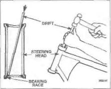
9.4 Drive the bearing outer races out with a brass drift as shown
retainer cage for signs of cracks or splits. Spin the bearings by hand. They should spin freely and smoothly. If there are any signs of wear on any of the above components both upper and lower bearing assemblies must be renewed as a set. Only remove the outer races from the frame headstock if they need to be renewed - do not re-use them once they have been removed.
Renewal
4 The outer races are an interference fit in the frame headstock and can be tapped from position with a suitable drift (see illustration). Tap firmly and evenly around each race to ensure that it Is driven out squarely. It may prove advantageous to curve the end of the drift slightly to improve access.
5 Alternatively, the races can be removed using a slide-hammer type bearing extractor; these can often be hired from tool shops.
6 The new outer races can be pressed into the head using a drawbolt arrangement (see illustration), or by using a large diameter tubular drift. Ensure that the drawbolt washer or drift (as applicable) bears only on the outer edge of the race and does not contact the working surface. Alternatively, have the races installed by a dealer equipped.
ИТТРИЯ Installation of new bearing
| HilUT |
outer races is made much
easier if the races are left overnight in the freezer. This
causes them to contract slightly
making them a looser fit.
7 To remove the lower bearing inner race from the steering stem, use two screwdrivers placed on opposite sides of the race to work it free. If the bearing is firmly in place it will be necessary to use a bearing puller, or In extreme circumstances to split the bearing's inner section using an angle grinder (see illustration). Take the steering stem to a dealer if required. Check the condition of the dust seal that fits under the inner race and renew it if it is worn, damaged or deteriorated.
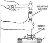
8 Fit the new lower bearing inner race onto the steering stem. A length of tubing with an

9.6 Drawbolt arrangement for fitting steering stem bearing outer races
1 Long bolt or threaded bar
2 Thick washer
3 Guide for lower race
internal diameter slightly larger than the steering stem will be needed to tap the new bearing into position (see illustration). Ensure that the drift bears only on the inner edge of the bearing race and does not contact its working surface. 9 Install the steering stem (see Section 8).
10 Rear shock absorber -
| I |
removal, inspection and installation
Removal
| 10.2 The heel plates are secured to the footrest brackets by two bolts (arrowed) |
1 Place the machine on an auxiliary stand. Position a support under the rear wheel so that it does not drop when the shock absorber is removed, but also making sure that the weight of the machine is off the rear suspension so that the shock is not compressed.
2 Remove the seat cowling (see Chapter 8).
MKH
|
| STEERING STEM |
9.7 It is best to remove the lower bearing using a puller
9.8 Drive the new bearing on using a suitable bearing driver or a length of pipe
On J and К models, unscrew the bolts securing both rider's heel plates and remove them (see illustration). On L, N and R models, unscrew the bolts securing the rider's left-hand heel plate and remove it. 3 On J and К models, using socket extensions inserted through the holes In the swingarm, counter-hold the shock absorber lower mounting bolt and unscrew the nut, then withdraw the bolt (see illustration) On L, N and R models, using a socket extension inserted through the hole in the left-hand side
10.3a Shock absorber lower mounting bolt (arrowed) - J and К models
6» 18 Frame, suspension and final drive

|

|

|
Дата добавления: 2015-10-29; просмотров: 142 | Нарушение авторских прав
| <== предыдущая страница | | | следующая страница ==> |
| Prise out the dust seal using a flat-bladed screwdriver | | | B Shock absorber lower mounting bolt (arrowed) - L, N and R models |