Читайте также:
|
is easier to disconnect the two-pin connector in the bracket behind the air filter housing (black/white and blue/yellow wires) rather than disconnecting the wiring from the terminals on the coils (see illustrations 3.5a and b and 3.7b). On L, N and R models, it is easier to disconnect the bullet connectors in the primary circuit wiring on top of the coils rather than disconnecting the wiring from the terminals on the coils (see illustration 3.5c). Mark the locations of all wires and leads before disconnecting them.
12 Unscrew the two bolts securing the coil
mounting bracket, and remove the coil
assembly. Note the routing of the HT leads. If
required, separate the individual coils from the
bracket, noting how they fit.
Installation
13 Installation is the reverse of removal.
Make sure the wiring connectors and HT
leads are securely connected.
Pulse generator coil
assembly - check, removal ^i
and installation ^
Check
|
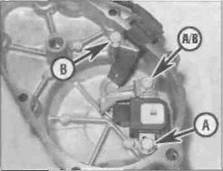
| 4.10 Unscrew the coil bolts (A) and the wiring guide bolts (B) - L, N and R models shown |
1 Remove the rider's seat (see Chapter 8) and disconnect the battery negative (-ve) lead.
2 Remove the lower fairing (see Chapter 8) and the fuel tank (see Chapter 4).
B Pulse generator coil wiring connector (arrowed) - L, N and R models
3 Trace the pulse generator coil switch wiring back from the starter clutch cover on the left-hand side of the engire and disconnect it at the red 4-pin connector (J and К models) or the brown 2-pin connector (L, N and R models) (see illustrations). Us ng a multimeter set to the ohms x 100 scale, -neasure the resistance between the white/yellow and yellow terminals on the pulse generator coil side of the connector. On J and К models with two coils, also measure the resistance between the white/blue and blue terminals.
4 Compare the reading obtained with that given in the Specifications at the beginning of this Chapter. The pulse generator coil(s) must be renewed if the reading obtained differs greatly from that given, particularly if the meter indicates a short circuit (no measurable resistance) or an open circuit (infinite, or very high resistance). On J and К models, even if only one of the coils is faulty both must be renewed as they come as an assembly.
5 If the pulse generator coil is thought to be faulty, first check that this is not due to a damaged or broken wire from the coil to the connector; pinched or broken wires can usually be repaired.
Removal
6 Remove the seat (see Chapter 8) and disconnect the battery negative (-ve) lead.
7 Remove the lower fairing (see Chapter 8) and the fuel tank (see Chapter 4).
8 Trace the pulse generator coil wiring back from the starter clutch cover on the left-hand side of the engine and disconnect it at the red 4-pin connector (J and К models) or the brown 2-pin connecter (L. N and R models) (see illustrations 4.3a or b). Feed the wiring through to the cover, noting its routing.
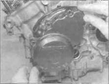
9 Unscrew the bolts securing the starter clutch cover and remove the cover, being prepared to catch any residue oil (see illustration). Discard the gasket as a new one must be used. Remove the dowel from either the cover or the crankcase if it is loose.
10 Unscrew the bolts securing the pulse
generator coil(s) and the wiring guide to the
inside of the cover (see illustration). Remove
the rubber wiring grommet from its recess,
then remove the coil(s).
Ignition system 5*5

|
|

|
4.13a Locate the new gasket onto the dowel (arrowed)...
Дата добавления: 2015-10-29; просмотров: 195 | Нарушение авторских прав
| <== предыдущая страница | | | следующая страница ==> |
| Primary circuit connectors from the coils | | | B ... then install the cover |