Читайте также:
|
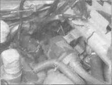
| 14.16b... and detach the drain hose from the underside |
the seat cowling to access all areas (see Chapter 8).
|
| 14.16a Pull the pump off its mounts... |
2 The fuel pump is controlled through the fuel cut-off relay so that it runs whenever the ignition is switched ON and the ignition is operative (ie, only when the engine is turning over). As soon as the ignition is killed, the relay will cut off the fuel pump's electrical supply (so that there is no risk of fuel being sprayed out under pressure in the event of an accident).
3 It should be possible to hear or feel the fuel pump running whenever the engine is turning over - either place your ear close beside the pump or feel it with your fingertips. If you can't hear or feel anything, check the circuit fuse (see Chapter 9). If the fuse is good, check the pump and relay for loose or corroded connections or physical damage and rectify as necessary.
4 If the circuit is fine so far, switch the ignition OFF. Unplug the relay's wiring connector and connect across the relay's black and black/blue wire terminals with a short length of insulated jumper wire. Switch the ignition ON: the pump should operate Turn OFF the ignition and disconnect the jumper wire when testing is complete.
5 If the pump operated when tested as described in Step 4 either the relay or its wiring is at fault.
6 If the pump still did not operate, trace the wiring from the pump and disconnect It at the black 2-pin wiring connector (see illustrations). Using a fully charged 12 volt
battery and two insulated jumper wires, connect the positive (+ve) terminal of the battery to the pump's black/blue wire terminal, and the negative (-ve) terminal of the battery to the pump's green wire terminal. The pump should operate. If the pump does not operate it must be renewed. Disconnect the battery and jumper wires.
7 Honda do not provide any test details for the relay, so the best way to determine whether it is faulty is by substituting a known good one. If the pump now works, the old relay is proven faulty. If the pump still does not work, check all the wiring and connectors between the pump and relay, and between the relay and the other components In the system, using the wiring diagrams at the end of Chapter 9. If this does not cure the problem, bear in mind that the ignition control unit could be faulty.
8 If the pump operates but is thought to be delivering an insufficient amount of fuel, first check that all fuel hoses are in good condition and not pinched or trapped. Check that the fuel filters in the fuel tank and fuel delivery hose are not blocked.
9 The fuel pump's output can be checked as follows: make sure the ignition switch is OFF.

|
10 Release the clamp securing the fuel supply hose to the inlet union on the carburettors and detach the hose, being prepared for any residual fuel (see illustration 7.5). Place the end into a graduated beaker.
11 Disconnect the fuel cut-off relay wiring connector. Using a short length of insulated
jumper wire, connect across the black and the black/blue wire terminals of the connector.
12 Turn the ignition switch ON and let fuel flow from the pump into the beaker for exactly 5 seconds, then switch the ignition OFF.
13 Measure the amount of fuel that has flowed into the beaker, then multiply that amount by 12 to determine the fuel pump flow rate per minute. The minimum flow rate required is 660 cc per minute on J and К models, and 700 cc per minute on L, N and R models. If the flow rate recorded is below the minimum required, then the fuel pump must be renewed.
Removal
14 Make sure both the ignition and the fuel tap are switched OFF. On L. N and R models, displace the carburettors from the inlet manifolds and positior them clear to provide access to the fuel pump (see Section 7). There should be no need to disconnect the throttle cables, though care must be taken to properly support the carburettors. Remove them completely if required.
15 Trace the wiring from the fuel pump and disconnect it at the black 2 pin connector (see illustrations 14.6a or b).
16 Make a note or sketch of which fuel hose fits where as an aid to installation. Using a rag to mop up any spilled fjel. disconnect the two fuel hoses from the fuel pump (see illustration 14.1a). Displace the pump with its rubber mounting sleeve from the mounting bracket, then turn it to access the drain hose on the underside and detach the hose (see illustrations). Remove the pump.
17 To remove the fuel cut-off relay, disconnect the relay wiring connector and remove the relay from its mounting lug.
Installation
18 Installation is a reverse of the removal
procedure. Make sure the fuel hoses are
correctly and securely "itted to the pump - the
hose from the In-line filter attaches to the
union marked INLET; the hose to the
carburettors attaches to the other union. Start
the engine and check carefully that there are
no leaks at the pipe connections.
5И
Chapter 5
Ignition system
Contents
General information............................................................................ 1
Ignition control unit - check, removal and installation.................. 5
Ignition (main) switch - check, removal and installation.see Chapter 9
Ignition ИТ coils - check, removal and installation..................... 3
Ignition system - check...................................................................... 2
Ignition timing - general information and check.............................. 6
Degrees of difficulty
Neutral switch - check and replacement...................... see Chapter 9
Pulse generator coil assembly - check, removal
and installation......................................................................... 4
Sidestand switch - check and replacement............... see Chapter 9
Spark plugs - gap check and renewal......................... see Chapter 1
Throttle position sensor - check and replacement...................... 7
Easy, suitable for novice with little experience
I
Fairly easy, suitable |k
for beginner with
some experience 2S
Дата добавления: 2015-10-29; просмотров: 153 | Нарушение авторских прав
| <== предыдущая страница | | | следующая страница ==> |
| A Slacken the bracket screw (arrowed) and release the outer cable ... | | | Fairly difficult, |