|
Читайте также: |
| .v |
suitable for competent Jjj^
DIY mechanic ^jS
Difficult, suitable for |k
experienced DIY ^
mechanic ^
Very difficult,
suitable for expert or professional
DIY J
Specifications
Note: Models are identified by their production code letter - refer to 'Identification numbers' at the front of this manual for details.
Fuel
Grade................................................................................................... Unleaded, minimum 91 RON (Research Octane Number)
Fuel tank capacity................................................................................. 15.0 litres
Carburettors
Type....................................................................................................... CV
Pilot screw setting (turns out)
J and К models.................................................................................. 2 1/2 turns out
L, N and R models........................................................................... 2 1/4 turns out
Float height
J and К models.................................................................................. 7.0 mm
L, N and R models........................................................................... 13.7 mm
Idle speed.............................................................................................. see Chapter 1
Carburettor jet sizes
Pilot jet
J models............................................................................................. 40
K, L, N and R models....................................................................... 35
Main jet
J models............................................................................................. 115
К models............................................................................................. 105
L and N models................................................................................. 108
R models............................................................................................ 105
4*2 Fuel and exhaust systems
Torque settings
Note: Where a specified setting is not given for a particular bolt, the genera/ settings listed at the beginning apply. The dimension given applies to the diameter of the thread, not the head.
5 mm bolt/nut......................................................................................... 5 Nm
6 mm bolt/nut......................................................................................... 10 Nm
8 mm bolt/nut.......................................................................................... 22 Nm
10 mm bolt/nut........................................................................................... 35 Nm
12 mm bolt/nut........................................................................................... 55 Nm
6 mm flange bolt with 8 mm head............................................................ 9 Nm
6 mm flange bolt/nut with 10 mm head................................................... 12 Nm
8 mm flange bolt/nut............................................................................... 27 Nm
10 mm flange bolt/nut............................................................................. 40 Nm
Exhaust downpipe nuts.......................................................................... 12 Nm
Exhaust and silencer mounting bolts (J and К models)........................ 27 Nm
|
1 General information and precautions
General information
The fuel system consists of the fuel tank, fuel tap, filters, fuel pump and relay, carburettors, fuel hoses and control cables.
There are two fuel filters, one is litted inside the fuel tank and is part of the tap, and the other is in the fuel line to the pump.
The carburettors used on all models are CV types. On all models there is a carourettor for each cylinder. For cold starting, a choke knob is mounted on the top yoke, and is connected to the carburettors by a cable.
Air is drawn into the carburettors via an air filter which is housed under the fuel tank.
The exhaust system is a four-into-one design.
Many of the fuel system service procedures are considered routine maintenance items and for that reason are included in Chapter 1.
Precautions
| A |
Warning: Petrol (gasoline) is extremely flammable, so take extra precautions when you work on any part of the fuel system. Don't smoke or allow open flames or bare light bulbs near the work area, and don't work in a garage where a natural gas-type appliance is present. If you spill any fuel on your skin, rinse it off immediately with soap and water. When you perform any kind of work on the fuel system, wear safety glasses and have a fire extinguisher suitable for a class В type fire (flammable liquids) on hand.
Always perform service procedures in a well-ventilated area to prevent a build-up of fumes.
Never work in a building containing a gas appliance with a pilot light, or any other form of naked flame. Ensure that there are no naked light bulbs or any sources of flame or sparks nearby.
Do not smoke (or allow anyone else to smoke) while in the vicinity of petrel (gasoline)
or of components containing it. Remember the possible presence of vapour from these sources and move well clear before smoking.
Check all electrical equipment belonging to the house, garage or workshop where work is being undertaken (see the Safety first! section of this manual). Remember that certain electrical appliances such as drills, cutters etc. create sparks in the normal course of operation and must not be used near petrol (gasoline) or any component containing It, Again, remember the possible presence of fumes before using electrical equipment.
Always mop up any spilt fuel and safely dispose of the rag used.
Any stored fuel that is drained off during servicing work must be kept in sealed containers that are suitable for holding petrol (gasoline), and clearly marked as such; the containers themselves should be kept in a safe place. Note that this last point applies equally to the fuel tank if it is removed from the machine; also remember to keep its filler cap closed at all times.
| 2.2 Remove the fuel tap knob... |
Read the Safety first! section of this manual carefully before starting work.
| Models are identified by | ||
| HilUT | their production code letter - refer to 'Identification | |
| numbers' at the front of this manual for details. |
2 Fuel tank and fuel tap -
removal and installation
| A |
Warning: Refer to the precautions given in Section 1 before starting work.
Fuel tank
Removal
1 Make sure the fuel filler cap is secure and fuel tap is in the OFF position. On J and К models, remove the seat cowling (see Chapter 8). On L, N and R models, remove the rider's seat (see Chapter 8).
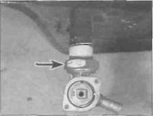
2 Remove the screw from the centre of the fuel tap knob and remove the knob (see illustration).
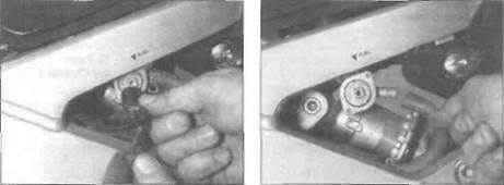
3 Place a rag under the fuel tap to catch any residual fuel as the hose is detached. Release the clamp securing the fuel hose to the tap and detach the hose (see illustration).
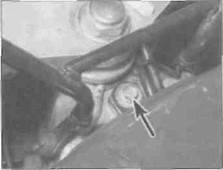
4 Unscrew the bolt securing the front of the tank to the frame anc carefully lift the tank away (see illustrations).
5 Inspect the tank mounting rubbers for signs of damage or deterioration and renew them if necessary.
Installation
| 2.3... then detach the fuel hose |
6 Check that the tank mounting rubbers and
the collar for the front mounting are fitted,
then carefully lower the fuel tank into position.
Fuel and exhaust systems 4*3
|
|
|
2.4a Unscrew the bolt at the front (arrowed)...
Дата добавления: 2015-10-29; просмотров: 161 | Нарушение авторских прав
| <== предыдущая страница | | | следующая страница ==> |
| A Access to the inner hose (arrowed) is restricted | | | L, N and Ft models |