Читайте также:
|
4 Remove the fuel tank (see Section 2).
5 Slacken the clamps securing the housing to the air inlet ducts at the front, then release the clamps securing the engine breather hoses to the unions on the front of the housing and detach the hoses (see illustration). If access is too restricted, this can be done after the housing has been displaced from the carburettors.
6 Slacken the clamps securing the housing to the carburettor inlet ducts at the back (see
|

|

|
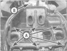
Remove the screws (A) and the bolt (B)...
4.3... then lift the housing and detach the hose (arrowed)
Slacken the clamps (A) and detach the hose (B) on each side...
4»4 Fuel and exhaust systems

|

|

4.6... then slacken the four clamps (A)
and detach the sub-air cleaner by
removing the screw (B)...
4.7... and remove the housing
air duct (arrowed)
illustration). Also remove the screw securing the sub-air cleaner to the rear of the housing and displace it.
7 Lift the housing up off the carburettors and
remove it.
Installation
8 Installation is the reverse of removal. Check
the condition of the breather rose(s) and
clamp(s) and renew them if necessary. On J
and К models, make sure the coller is in place
in the front mounting rubber. On L, N and R
models, make sure the inlets locate correctly
onto the air ducts and tighten the clamps (see
illustration).
5 Idle fuel/air mixture adjustment -
general information

|
| 7.4a Disconnect the throttle position sensor wiring connector... |
1 The pilot screws (see illustration 8.12a or 8.12b) are set to their correct position by the manufacturer and should not be adjusted or removed unless it is necessary to do so during a carburettor overhaul. If the screws are to be removed, record the pilot screw's current setting by turning the screw It in until it seats lightly, counting the number of turns necessary to achieve this, then fully unscrew it. On installation, the screw is simply backed out the number of turns you've recorded.
2 If the engine runs extremely rough at idle or continually stalls, and if a carburettor overhaul
does not cure the problem, take the motorcycle to a dealer equipped with an exhaust gas analyser. They will be able to properly adjust the idle fuel/air mixture to achieve a smooth idle and restore low speed performance.
6 Carburettor overhaul -
general information

|
| 7.4b... and release the idle speed adjuster |
1 Poor engine performance, hesitation, hard starting, stalling, flooding and backfiring are all signs that major carburettor maintenance may be required.
2 Keep in mind that many so-called carburettor problems are really not carburettor problems at all, but mechanical problems within the engine or ignition system malfunctions. Try to establish for certain that the carburettors are in need of maintenance before beginning a major overhaul.
3 Check the fuel tap and filters, the fuel hoses, the fuel pump and its relay, the Inlet manifold joint clamps, the air filter, the ignition system, the spark plugs and carburettor synchronisation before assuming that a carburettor overhaul is required.
4 Most carburettor problems are caused by dirt particles, varnish and other deposits which build up in and block the fuel and air passages. Also, In time, gaskets and O-rings
shrink or deteriorate and cause fuel and ait-leaks which lead to poor performance.
5 When overhauling the carburettors. disassemble them completely and clean the parts thoroughly with a carburettor cleaning solvent and dry them with filtered, unlubricated compressed air. Blow through the fuel and air passages with compressed air to force out any dirt that may have been loosened but not removed by the solvent. Once the cleaning process is complete. reassemble the carburettor using new gaskets and O-rings.
6 Before disassembling the carburettors. make sure you have all necessary O-rings and other parts, some carburettor cleaner, a supply of clean rags, some means of blowing out the carburettor passages and a clean place to work. It Is recommended that only one carburettor be overhauled at a time to avoid mixing up parts.
7 Carburettors -
removal and installation ^
| A |
Warning: Refer to the precautions given in Section 1 before starting work.
Removal
1 Remove the fuel tank and the air filter housing (see Sections 2 and 4). On L, N and R models, remove the rear trim panels (see Chapter 8).
2 Detach the choke cable from the carburettors (see Section 12, Step 2).
3 Detach the throttle cables from the carburettors (see Section 11, Steps 3 and 4). If access is too restricted, detach them after the carburettors have been lifted off the cylinder head inlets.
4 On L, N and R models, disconnect the throttle position sensor wiring connector from the right-hand end of the carburettors (see illustration). Also release the idle speed adjuster from its holder and feed it through to the base of the carburettors (see illustration).
5 Release the clamp securing the fuel supply
Fuel and exhaust systems 4*5
Дата добавления: 2015-10-29; просмотров: 139 | Нарушение авторских прав
| <== предыдущая страница | | | следующая страница ==> |
| Fairly difficult, | | | Release the clip and detach the fuel hose |