Читайте также:
|
Bracket so that the nut is against the lug
(arrow) and fully tighten the adjuster
Locate the nut (A) so it is captive,
Then set the freeplay by turning the
Adjuster (B) and tighten the locknut (C)
Against the bracket
7 Fit the rear half of the housing onto the handlebar, making sure the pin locates in the hole in the handlebar, and install the screws, tightening them securely (see illustration and 11.5b).
8 Feed the cables through to the carburettors, making sure they are correctly routed. The cables must not interfere with any other component and should not be kinked or bent sharply.
9 Lubricate the decelerator cable nipple with multi-purpose grease and fit it into the lower socket on the carburettor throttle cam (see illustration 11.4b). Fit the cable holder Into the lower bracket, locating the nut against the lug so that it is captive, then thread the holder Into the nut until it is tight (see illustration).
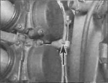
10 Lubricate the accelerator cable nipple with multi-purpose grease and fit it Into the upper socket on the carburettor throttle cam (see illustration 11.3b). Fit the accelerator cable adjuster into the upper bracket, then thread the lower nut up the adjuster (see illustration 11.3a). Locate the nut against the lug so that it Is captive, then thread the adjuster into the nut until the specified amount of cable freeplay is obtained (see illustration) (see Chapter 1). Tighten the locknut against the bracket.
11 Operate the throttle to check that it opens and closes freely.
12 Check and adjust the throttle cable freeplay if required (see Chapter 1). Turn the
handlebars back and forth to make sure the cable doesn't cause the steering to bind.
13 Install the carburettors (if displaced), the air filter housing and the fuel tank (see Sections 7, 4 and 2).
14 Start the engine and check that the idle speed does not rise as the handlebars are turned. If it does, the throttle cables are routed incorrectly. Correct the problem before riding the motorcycle.
12 Choke cable- ||
removal and installation Ц
Removal
1 Remove the fuel tank and the air filter housing (see Sections 2 and 4).
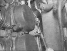
2 Slacken the choke outer cable bracket screw and free the cable from the bracket on the front of the carburettors, then detach the inner cable nipple from the choke linkage lever (see illustrations). Withdraw the cable from the machine noting the correct routing.
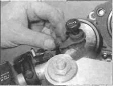
3 Unscrew the left-hand fork clamp bolt securing the choke knob to the top yoke and remove the cable (see illustration).
Installation
4 Locate the choke knob bracket against the top yoke and tighten the bolt securely.
5 Feed the cable through to the carburettors. making sure it is correctly routed. The cable must not interfere wit/i any other component and should not be kinked or bent sharply.
6 Lubricate the cable nipple with multipurpose grease and attach it to the choke linkage lever on the carburettor (see illustration 12.3b). Fit the outer cable into its bracket, making sure there is a small amount of freeplay in the inner cable, and tighten the screw (see illustration 12.3a).
7 Check the operation of the choke cable (see Chapter 1).
8 Install the air filter housing and the fuel tank (see Sections 4 and 2).
13 Exhaust system - ^
removal and installation §р
| A |
Warning: If the engine has been running the exhaust system will be very hot. Allow the system to cool before carrying out any work. Note: The exhaust system can be removed as a complete assembly. The silencer and downpipe assembly can be separated if required, but this is best done after the complete system has been removed, rather than doing it in situ.
|
|
|
Дата добавления: 2015-10-29; просмотров: 126 | Нарушение авторских прав
| <== предыдущая страница | | | следующая страница ==> |
| Nut is clear of its lug, then slip the cable | | | A Slacken the bracket screw (arrowed) and release the outer cable ... |