Читайте также:
|
Detach the neutral switch wiring connector

|
the bracket and slip the cable end out of the release lever (see illustrations)
17 Remove the front sprocket (see Chapter 6).
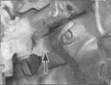
18 Disconnect the neutral switch wiring connector from the switch and secure it clear of the engine (see illustration).
19 At this point, position an hydraulic or mechanical jack under the engine with a block of wood between the jack head and sump (see illustration). Make sure the jack is centrally positioned so the engine will not topple when the last mounting bolt is removed. Take the weight of the engine on the jack.
J and К models
20 Remove the screw and detach the trim panel on each side of the frame (see illustration).
21 Unscrew and remove the engine upper front mounting bolts, and remove the oval spacer/washer fitted between the frame and engine on the right-hand bolt (see illustrations).
22 Unscrew the nuts on the engine lower front mounting bolts and withdraw the bolts, and remove the oval spacer/washer fitted between the frame and engine on the right-hand bolt and the hose guide fitted similarly on the left-hand bolt (see illustrations 5.21a, b and с and 5.22).
23 Make sure the engine is properly supported on the jack, and have an assistant support It as well.
24 Unscrew the nut on the engine lower rear mounting bolt and withdraw the bolt, and
remove the small spacer fitted between the engine and the frame on the left-hand side (see illustrations 5.21a and b and 5.24).

Position a jack under the engine

A Engine mounting bolts (A) and nuts (B) - right-hand side
Unscrew the bolts secunng the mounting bolt bracket to the right-hand side of the frame and remove the bracket.

Remove the screw (arrowed) and detach the trim panel on each side
B Engine mounting bolts (arrowed) -left-hand side
 | |

|
|
5.21c Oval spacers/washers (arrowed) with front right-hand bolts
Ш
Note the hose guide secured by the nut on the lower front left-hand bolt
Дата добавления: 2015-10-29; просмотров: 172 | Нарушение авторских прав
| <== предыдущая страница | | | следующая страница ==> |
| Cylinder compression - | | | L, N and R models |