Читайте также:
|
41 Position the 55 mm spacers for the upper
rear mounting bolt between the frame and the
engine, and slide the bolt through from the left
(see illustrations). Slide the adjusting
bolt onto the right-hand end (see illus
tration 5.31b) and tighten it to the torque
setting specified at the beginning of the Chapter
- you will have to push the mounting bolt back
out a bit to allow an Allen key into the adjusting
bolt (see illustration). Make a reference mark
between the adjusting bolt and the frame as a
check against the bolt turning while the locknut
is being tightened (see illustration), then fit the
locknut (see illustration 5.31a) and tighten it to the specified torque setting using the peg spanner or socket (see illustration). Check that the reference marks still align - if they don't, repeat the installation and tightening procedure. Now push the mounting bolt fully through from the left and fit the nut onto its right-hand end (see illustration). Tighten it hand-tight only at this stage.
42 Slide the lower rear mounting bolt through from the left-hand side (see illustration 5.30). Rt the nut, tightening it hand-tight only at this stage.
43 Position the 23 mm spacer for the right-hand middle bolt between the frame and engine, then install the middle bolts and tighten them hand-tight only (see illustration 5.28).
44 If removed, install the front mounting bolt brackets (see illustration 5.27). Position the 19 mm spacers for the front bolts between the brackets and engine, then install the bolts and tighten them hand-tight only.
45 Now tighten all the nuts and bolts to the torque settings specified at the beginning of the Chapter.
All models
46 The remainder of the installation
procedure is the reverse of removal, noting
the following points.
a) Make sure all wires, cables and hoses are correctly routed and connected, and secured by the relevant clips or ties.
b) Adjust the throttle and clutch cable freeplay (see Chapter 1),
c) Adjust the drive chain (see Chapter 1).
d) Refill the engine with oil and coolant (see Chapter 1).
e) Prior to installing the lower fairing panels start the engine and check that there are no signs of coolant/oil leakage.
6 Engine disassembly and reassembly -
general information
Disassembly
1 Before disassembling the engine, the external surfaces of the unit should be thoroughly cleaned and degreased. This will prevent contamination of the engine internals, and will also make working a lot easier and cleaner. A high flash-point solvent, such as paraffin (kerosene) can be used, or better still, a proprietary engine degreaser. Use old paintbrushes and toothbrushes to work the solvent Into the various recesses of the engine casings. Take care to exclude solvent or water from the electrical components and inlet and exhaust ports.
| A |
Warning: Trie use of petrol (gasoline) as a cleaning agent should be avoided because of the risk of fire.
2«12 Engine, clutch and transmission

|
|

|
7.3 Slacken the hose clamps and detach
the hoses (A), then unscrew the bolt (B) -
L, N and R models shown
7.5a Fit a new O-ring...
7.5b... then install the cooler, locating the bracket over the lug (arrowed)...
2 When clean and dry, arrange the unit on the workbench, leaving suitable clear area for working. Gather a selection of small containers and plastic bags so that parts can be grouped together in an easily identifiable manner. Some paper and a pen siould be on hand so that notes can be made and labels attached where necessary. A supply of clean rag is also required.
3 Before commencing work, read through the appropriate section so that some idea of the necessary procedure can be gained. When removing components it should be noted that great force is seldom required, unless specified. In many cases, a component's reluctance to be removed is Indicative of an incorrect approach or removal method - if in any doubt, re-check with the text.
4 When disassembling the engine, keep 'mated' parts together (Inducing gears, pistons, connecting rods, valves, etc. that have been in contact with each other during engine operation). These 'mated' parts must be reused or renewed as an assembly.
5 A complete engine/transmission disassembly should be done In the following general order with reference to the appropriate Sections.
Remove the valve cover
Remove the camshafts
Remove the cylinder head
Remove the thermostat housing (L, N and
R models) (see Chapter 3) Remove the cylinder block and pistons (J
and К models) Remove the starter clutch Remove the clutch
Remove the alternator (see Chapter 9) Remove the starter motor (see Chapter 9) Remove the water pump (see Cnapter3) Remove the gearchange mechanism
external components Remove the oil sump Remove the oil pump Separate the crankcase halves Remove the connecting rods (and pistons
on L, N and R models) Remove the crankshaft Remove the transmission shafts Remove the selector drum and forks
Reassembly
6 Reassembly is accomplished by reversing the general disassembly sequence.
7 Oil cooler - |$a
removal and installation ^
Note: The oil cooler can be removed with the engine in the frame. If the engine has been removed, ignore the steps which do not apply.
Removal
1 Remove the lower fairing (see Chapter 8).
2 Drain the engine oil and remove the oil filter (see Chapter 1). Drain the cooling system (see Chapter 1), or have some means of blocking or clamping the hoses to avoid excessive loss of coolant (see 'Section 9 Hoses' in the Tools and Workshop Tips section at the end of this manual).
3 Slacken the clamp securing each hose to the cooler and detach the hoses (see illustration).
4 Unscrew the cooler bolt using a 30 mm socket and remove the cooler, noting how the cutout in the bracket locates over the lug on the crankcase (see illustration 7.5b). Discard the cooler O-rlng as a new one must be used.
Installation

|
| 7.5c... and tighten the bolt to thespecified torque |
5 Installation is the reverse of removal, noting the following:
a) Always use a new O-ring when installing the cooler (see illustration).
b) Locate the bracket on the cooler over the lug on the crankcase (see illustration).
c) Tighten the cooler bolt to the torque setting specified at the beginning of the Chapter (see illustration).
d) Make sure the coolant hoses are pressed fully onto their unions and are secured by the clamps (see illustration 7.3).
e) Fit a new oil filter and fill the engine with oil (see Chapter 1).
f) Refill the cooling system if it was drained, or check the level in both the radiator and the reservoir and top up if necessary (see Chapter 1).
8 Valve cover - ^
removal and installation ^,
Note: The valve cover can be removed with the engine in the frame. If the engine has been removed, ignore the. steps which do not apply.
Removal
|
| 8.2a Release the hose from itsclip... |
1 Remove the lower fairing (see Chapter 8).
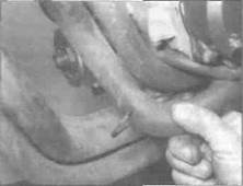
2 Release the lower radiator hose from its clip on the left-hand side of the engine, then unscrew the radiator lower mounting bolt(s) and swing the bottom of the radiator forward {see illustrations). To provide better
Engine, clutch and transmission 2»13

|
|

|
8.2b... then unscrew the bolt(s) and swing the radiator forward
8.6 Unscrew the bolts (arrowed) and remove the cover
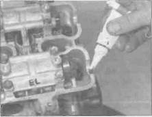
8.9a Apply the sealant as described...
clearance, and to avoid scratching anything, it is better to remove the radiator (see Chapter 3).
3 Disconnect the spark plug caps from the plugs and secure them clear of the engine. noting which fits where.
4 For best access, remove the air filter housing (see Chapter 4). On L. N and R models, also remove the Ignition HT coils (see Chapter 5), then remove the heat shield. noting how it fits.
5 If the air filter housing was not removed. release the clamp securing the breather hose to the breather on the top of the valve cover and detach the hose.
6 Unscrew the eight bolts securing the valve cover then lift the cover off the cylinder head (see illustration). If It is stuck, do not try to lever it off with a screwdriver. Tap it gently around the sides with a rubber hammer or block of wood to dislodge it. Also remove the gasket. Note the rubber washers fitted in the cover and remove them if they are loose.
Installation
7 Examine the valve cover gasket and the rubber washers for signs of damage or deterioration and renew them if necessary.
8 Clean the mating surfaces of the cylinder head and the valve cover with lacquer thinner, acetone or brake system cleaner.
9 Apply a smear of a suitable sealant into the
grooves in the valve cover and into the cutouts in the cylinder head. Install the gasket onto the valve cover, making sure it fits correctly into the groove (see illustrations).
10 The valve cover must be installed with the arrow on its top pointing to the front. Position the valve cover on the cylinder head, making sure the gasket stays in place (see illustration). If removed, fit the rubber washers into the cover, using new ones If required, and making sure they are installed with the 'UP' mark facing up. Install the cover bolts and tighten them to the torque setting specified at the beginning of the Chapter.
11 Install the remaining components in the reverse order of removal.
9 Camshafts - removal,
inspection and installation ^
Note: The camshafts can be removed with the engine in the frame. Place rags over thei spark plug holes and the cam gear train hole to prevent any component from dropping Into the engine on removal.
Removal
1 Remove the valve cover (see Section 8).
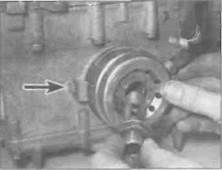
2 Unscrew the timing inspection plug and the centre plug from the alternator cover on the

8.9b... then fit the gasket onto the cover...
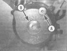
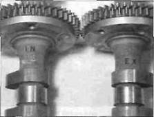
right-hand side of the engine (see illustration). Discard the plug O-rlngs as new ones should be used. The engine can be turned using a 14 mm socket on the alternator rotor bolt and turning it in a clockwise direction only (see illustration). Alternatively, place the motorcycle on an auxiliary stand so that the rear wheel is off the ground, select a high gear and rotate the rear wheel by hand in its normal direction of rotation. 3 Turn the engine until the line next to the T mark on the alternator rotor aligns with the notches in the timing inspection hole, and the 'IN' mark on the inlet camshaft gear and the 'EX' mark on the exhaust camshaft gear are aligned with the cylinder head surface with each mark the correct way up and on the outside of its respective gear (see
|

|

|
8.10... and install the cover
9.2a Remove the timing inspection plug (A) and the centre plug (B)
9.2b Turn the engine clockwise using a 14 mm socket on the alternator rotor bolt
2*14 Engine, clutch and Transmission

|
| ■"J | |
| F | ■ - ". |
| У¥^\Щ | |
| > | чч^В^ ^ |
9.3a Turn the engine until the Tl mark (A) aligns with the static marks (B)...
9.3b... and the camshaft gear marks align as described and shown

|
9.5a Camshaft holder bolts (arrowed)
9.5b Remove the camshafts.
illustrations). If the 'IN' and 'EX' marks are upside down and on the inside of their respective gears, turn the engine one full turn (360°) until the line next to the T mark again aligns with the notches. The 'IN' and 'EX' marks will now be correctly aligned.
4 Before disturbing the camshaft holders, check them for identification markings. The inlet camshaft holders are marked INR (right-hand side) and INL (left-hand side) and the exhaust camshaft holders marked EXR (right-hand side) and EXL (left-hand side). These markings ensure that the holders can be matched up to their original locations on installation. If no markings are visible, make your own using a felt pen. If necessary, make a sketch of the layout as a further aid for installation.
5 Unscrew the camshaft holder bolts for the camshaft being worked on, evenly and a little at a time in a criss-cross pattern, until they are
all loose (see illustration). While slackening the bolts make sure that the holder is lifting squarely away from the cylinder head and is not sticking on the locating dowels. Caution: If the bolts are carelessly loosened and the holder does not come squarely away from the head, the holder is likely to break. If this happens the complete cylinder head assembly must be renewed; the holders are matched to the cylinder head and cannot be renewed separately. Also, a camshaft could break if the holder bolts are not slackened evenly and the pressure from a depressed valve causes the shaft to bend. Remove the bolts, then lift off the camshaft holders, noting how they fit. Retrieve the dowels from either the holder or the cylinder head if they are loose. Lift each shaft out of the head (see illustration), The camshafts are marked for identification. The inlet camshaft is
marked 'IN' and the exhaust camshaft is marked 'EX' (see illustration).
Inspection
6 Inspect the bearing surfaces of the camshaft holders and the corresponding
9.6c... noting the identification marks
Engine, clutch and transmission 2*15
Дата добавления: 2015-10-29; просмотров: 131 | Нарушение авторских прав
| <== предыдущая страница | | | следующая страница ==> |
| B ... and the clutch cable | | | Plastigauge container |