|
Читайте также: |
2»16 Engine, clutch and transmission

9.16 Apply molybdenum oil to the camshaft journals and holders...
15 Check the camshaft drive gear on the
drive gear assembly and the driven gear on
each camshaft for wear, cracks and other
damage, renewing them if necessary. The
driven gears are integral with the camshafts.
whilst the drive gear assembly can be
removed from the engine (see Section 13). If
wear this severe is apparent, the entire engine
should be disassembled for inspection.
Installation
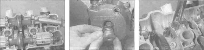
16 Make sure the bearing surfaces on the camshafts and in the holders are clean, then apply molybdenum disulphide oil (a 50/50 mixture of molybdenum disulphide grease and engine oil) to each of them (see illustration). Also apply it to the camshaft lobes and the followers.
17 The camshafts and holders must be installed in their correct location according to their identification marks (see Steps 5 and 4).
18 Verify that the line next to the T mark on the alternator rotor is still aligned with the notch (see illustration 9.3a), then lay each camshaft into place (see illustration), engaging them with the drive gear assembly, and making sure all the marks are in exact alignment (see Step 3) (see illustration 9.3b). Take extra care at this stage as it is easy to be one tooth out on the timing without it appearing as a drastic misalignment of the timing marks.
19 Make sure the camshaft holder dowels are in position then fit the holde-s. making
| I " | |
| в | ! |
| Ш |
9.18... then install the camshafts...
sure they are in their correct location (see Step 4) (see illustration). Tighten the holder bolts evenly and a little at a time in a crisscross pattern to the torque setting specified at the beginning of the Chapter, starting with the bolts that are closest to any valve which will be compressed by the camshaft lobes as the holders are tightened down (see illustration). This is to avoid placing undue strain on the camshafts. Whilst tightening the bolts, make sure the holders are being pulled squarely down and are not binding on the dowels. Check that each camshaft is not pinched by turning the engine a few degrees in each direction.
Caution: The camshaft is likely to break if it is tightened down onto the closed valves before the open valves. The holders are likely to break if they are not tightened down evenly and squarely.
20 With all holders tightened down, check
again that the valve timing marks still align
(see Step 3).
Caution: If the marks are not aligned exactly as described, the valve timing will be incorrect and the valves may strike the pistons, causing extensive damage to the engine.
21 Check the valve clearances and adjust them if necessary (see Chapter 1). This is essential if new components have been installed or if the camshafts were removed to change the shims.
22 Use new O-rings on the timing inspection

9.19a... and the holders...
plug and centre plug and smear them and the plug threads with molybdenum disulphide oil (a 50/50 mixture of molybdenum disulphide grease and engine oil) (see illustration). Tighten the plugs to the torque setting specified at the beginning of the Chapter. 23 Install the valve cover (see Section 8).
10 Cylinder head -
| I |
removal and installation
Caution: The engine trust be completely cool before beginning this procedure or the cylinder head may become warped. Note: To remove the cylinder head the engine must be removed from the frame.
Removal
1 Remove the engine from the frame (see Section 5).
2 Remove the camshafts (see Section 9).
3 Obtain a container which is divided into sixteen compartments, and label each compartment with the location of its corresponding valve in the cylinder head and whether It belongs with an inlet or an exhaust valve. If a container is not available, use labelled plastic bags. Lift each cam follower out of the cylinder head using either a magnet or a pair of pliers and store it in its corresponding compartment in the container (see illustration). Retrieve the shim from either the inside of the follower or pick it out of
|
9.19b... and tighten the holder bolts to the specified torque
9.22 Install the plugs using new O-rings
10.3a Remove the follower...
Engine, clutch and transmission 2*17
10.3b... and either retrieve the shim from inside the follower...
10.3c... or from the top of the valve, using either a magnet...
10.3d... or a screwdriver with grease on it
|
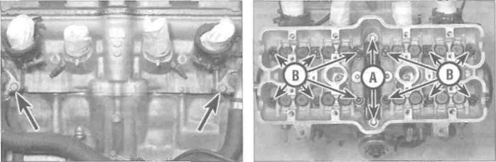
10.4 Unscrew the bolts (arrowed) and detach the pipes from the
head
10.5a Cylinder head bolts (A) and nuts (B)

|
the top of the valve, using either a magnet, a small screwdriver with a dab of grease on it (the shim will stick to the grease), or a screwdriver and a pair ot pliers (see illustrations). Do not allow the shim to fall into the engine.
4 Unscrew the bolt securing each coolant pipe in the rear of the cylinder head (see illustration). Pull each pipe out of the head. Discard the O-rings as new ones must be used.
5 Each cylinder head is secured by two bolts and twelve nuts (see illustration). First
10.5b Slide the nuts towards the centre so the base rim clears the casting
| 10.6 Lift the head up off the block |
slacken and remove the two bolts located in the cam drive gear tunnel. Now slacken the nuts evenly and a little at a time in a crisscross sequence, working from the outside towards the centre, until they are all slack, and remove the nuls by sliding them towards the centre as they are held captive by the casting (see illustration). 6 Pull the cylinder head up off the block (see illustration). If it is stuck, tap around the joint faces of the cylinder head with a soft-faced mallet to free the head. Do not attempt to free the head by inserting a screwdriver between
the head and cylinder block - you'll damage the sealing surfaces. Remove the old cylinder head gasket and discard it as a new one must be used.
7 If they are loose, remove the two dowels from the cylinder block. If they appear to be missing they are probably stuck in the underside of the cylinder head.
8 Check the cylinder head gasket and the mating surfaces on the cylinder head and block for signs of leakage, which could indicate warpage. Refer to Section 12 and check the flatness of the cylinder head.
9 Clean all traces of old gasket material from the cylinder head and block. If a scraper is used, take care not to scratch or gouge the soft aluminium. Be careful not to let any of the gasket material fall into the crankcase, the cylinder bores or the oil passages.
Installation
10 If removed, install the dowels onto the outer rear studs and press them into the cylinder block (see illustration 10.11). Lubricate the cylinder bores with engine oil.
11 Ensure both cylinder head and block mating surfaces are clean, then lay the new head gasket in place on the cylinder block, making sure all the holes are correctly aligned,
2*18 Engine, clutch and transmission

|
Дата добавления: 2015-10-29; просмотров: 162 | Нарушение авторских прав
| <== предыдущая страница | | | следующая страница ==> |
| L, N and R models | | | Make sure the gasket locates onto the dowels (A) and the UP mark (B) reads correctly |