Читайте также:
|
required, remove the throttle posi:ion sensor (see Chapter 5).
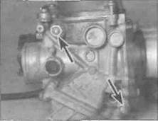
3 On J and К models, remove the screw securing the sub-air cleaner to the air duct holder {see illustration). Bend back the tabs on the lockplates between each pair of screws securing the air duct hoder to the carburettors, then remove the screws and lift off the duct holder, noting which way round it fits and how it locates onto the dowels. Also note how the rubber flanges locate around the air pipes. Remove the dowels from each carburettor inlet if they are loose. Discard the lockplates as new ones should be used. Remove the screws securing the idle speed adjuster bracket to the float chambers on Nos. 1 and 2 carburettors and detach the bracket (see illustration 8.7b). Remove the screws securing the choke actuating lever bracket to the top of the carburettors and remove the bracket (see illustration). Slacken all the choke plunger actuating arm screws and lift the arms off the plungers (see illustration). Remove the screws sscuring the joining plate to the top of the carburettors and remove the plate (see illustration).
4 On L, N and R models, remove the screws securing the choke plunger linkage bar to the carburettors, then remove the plastic washers (see illustration 8.14a). Lift off the bar and remove the return spring, noting how they fit, and remove the collars (see illus-
tration 8.14b). Unscrew the nut on one end of each threaded stud which joins the carburettors together, then withdraw the bars (see illustration).
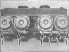
5 Make a careful note of how the carburettor synchronisation springs and throttle linkage springs are arranged to ensure that they are fitted correctly on reassembly (see illustration). Also note the arrangement of the various hoses and their unions.
6 Carefully separate the carburettors, taking care not to damage the fuel and air vent joints between each carburettor or lose the screws from the throttle linkages. Keep a careful watch on all springs as the carburettors are separated; the synchronisation springs should stay with the adjusting screws, but if they don't, find them and install them so they aren't lost. On J and К models, note how the choke actuating arms, return spring and bar are fitted and come apart as the carburettors are separated as an aid to installation.
7 Pull out the fuel fittings and vent line fittings and the joining pieces and discard the O-rinys where fitted as new ones must be used.
Joining
8 Assembly is the reverse of the disassembly
procedure. Use new O-rings on the fuel and
vent line fittings, and smear them with oil.
Check the operation of both the choke and
throttle linkages ensuring that both operate
smoothly and return quickly under spring pressure before installing the carburettors on the machine. Check carburettor synchronisation (see Cnapter 1).
10 Carburettors - reassembly
and float height check *^
| A |
Warning: Refer to the precautions given in Section 1 before proceeding.
Note: When reassembling the carburettors, be sure to use new O-rings and seals. Do not overtighten the carburettor jets and screws as they are easily damaged.
1 If removed, install the choke plunger assemblies into the carburettor bodies.
2 On J and К models, locate the actuating arms on the choke plungers (see illustration 8.13). Align the actuating arms so that the gap between them and еаст plunger is equidistant (so that each plunger opens simultaneously when the choke is activated), then tighten the clamp screws onto the bars.
3 On L, N and R models, fit the choke linkage bar collars, then locate the return spring and the bar, making sure the arms fit onto the plungers, then fit the plastic washers and secure the bar with the screws (see illustrations 8.14b and a).
|
|

|
Дата добавления: 2015-10-29; просмотров: 131 | Нарушение авторских прав
| <== предыдущая страница | | | следующая страница ==> |
| B ... noting how the arms locate on the plungers (A) and the return spring (B) fits | | | Nut is clear of its lug, then slip the cable |