|
Читайте также: |
Engine, clutch and transmission 2*35
|
20.12a Locate the pin (A) in the slot (B)...
20.12b... and install the bolt using thread-lock
|
Inspection
8 Inspect the stopper arm return spring and the shaft centralising spring. If they are fatigued, worn or damaged they must be renewed. Also check that the centralising spring locating pin in the casing is securely tightened. If it is loose, remove it and apply a suitable non-permanent thread-locking compound, then tighten it to the specified torque.
9 Check the gearchange shaft for straightness and damage to the splines. If the shaft is bent you can attempt to straighten it, but if the splines are damaged the shaft must be renewed. Also check the condition of the shaft oil seal in the casing and renew It if damaged or deteriorated. Lever the old seal out using a screwdriver and drive the new seal in squarely (see illustrations 20.30a and b).
10 Inspect the selector arm eye and the drum selector collar, and the stopper arm roller and the stopper plate. If they are worn or damaged they must be renewed.
11 Check the drum selector, pawls, pins and springs for wear and damage. Renew them if defects are found.
Installation
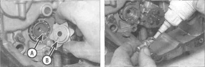
12 If removed, Install the locating pin in the
offset hole in the end of the selector drum.
Install the drum selector cam. locating the slot in its back over the locating pin in the selector drum (see illustration). Clean the threads of the pin bolt, then apply a suitable non-permanent thread-locking compound (see illustration). Install the pin bolt and tighten it securely.
| 20.14a Install the dowel... |
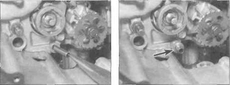
13 Fit the spacer onto the guide plate upper mounting dowel.
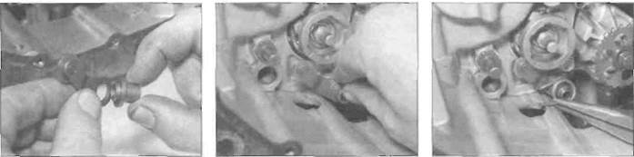
14 If removed, fit the stopper arm dowel into the lower bolt hole, and slide the thrust washer onto it (see illustrations). Fit the collar into the stopper arm (see illustration).
Fit the stopper arm assembly onto the lower mounting dowel, positioning the stopper arm onto the neutral detent on the stopper plate (identified by the line on the face of the cam) then fit the spring, making sure the ends are located correctly over the stopper arm and against the casing (see illustrations). Make sure the stopper arm is free to move and is returned by the pressure of the spring. 15 If the drum selector assembly was disassembled, install the springs, pins and pawls, making sure the rounded end of each pawl fits into the rounded cut-out in the drum
20.14b... and slide the washer (arrowed) onto it
|
20.14c Fit the collar into the arm
20.14d... and slide them onto the dowel...
20.14e... then position the arm and fit the spring
2*36 Engine, clutch and transmission
|
|
I<7
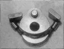
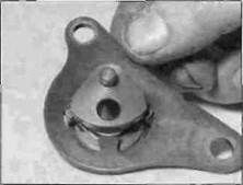
20.15a Drum selector pawl assembly
selector, and that the pins locate correctly in the cut-outs In the pawls (see illustrations).
16 Depress the pawls and tit the drum selector assembly into the guide plate (see illustration). Fit the assembly into the selector cam, locating the pin bolt through the hole in the drum selector (see illustration). Make sure the pawls locate correctly in the cutouts in the cam. Clean the threads ot the guide plate bolts, then apply a suitable non-permanent thread locking compound and tighten them securely (see illustration).
17 Fit the collar onto the pin on the drum selector assembly (see illustration 20.4b).
18 Check that the gearchange shaft centralising spring is correctly positioned. then fit the thrust washer onto the end of the shaft (see illustration). Fit the shaft into its
20.15b Note that the pawl cut-out is offset - ensure they are fitted correctly
hole in the casing (see illustration 20.4a). Make sure the centralising spring ends are correctly located on each side of the tab on the arm and the pin in the casing, and that the eye of the arm locates around the collar (see illustration). Remove the tape from around the splines.
19 Install the gearchange linkage arm onto the end of the shaft on the left-hand side of the engine, aligning the punch marks, and check that the mechanism works correctly (see illustrations 20.22). Tighten the pinch bolt.
20 Install the oil pump drive sprocket and chain, and the clutch (see Section 16).
Дата добавления: 2015-10-29; просмотров: 138 | Нарушение авторских прав
| <== предыдущая страница | | | следующая страница ==> |
| J and К models | | | L, N and R models |