Читайте также:
|
Removal
1 Make sure the transmission is in neutral. Remove the clutch and the oil pump drive sprocket and chain (see Section 16).
2 Unscrew the gearchange lever linkage arm pinch bolt and remove the arm from the shaft, noting the alignment punch marks (see illustration 20.22). If no marks are visible, make your own before removing the arm so that it can be correctly aligned with the shaft on Installation.
|
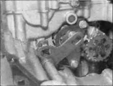
| 20.4a Withdraw the shaft... |
3 Wrap some insulating tape around the gearchange shaft splines to avoid damaging the oil seal as it is removed.
4 Note how the gearchange shaft centralising spring ends fit on each side of the locating pin in the casing, and how the eye of the selector arm locates over the collar on the drum shift assembly (see illustration 20.18b). Withdraw the gearchange shaft and its thrust washer from the casing (see illustration). Remove the collar from the pin on the drum selector assembly (see illustration).
5 Unscrew the two bolts securing the drum selector guide plate, then remove the plate along with the drum selector assembly, noting that the pawls of the selector assembly are under spring pressure (see illustration). Use
your fingers to prevent them from pinging out. Note the correct fitted position of all components. Remove the spacer from the guide plate upper mounting dowel.
6 Press the stopper arm down off the stopper plate on the selector drum and remove the arm with its return sp.'ing and collar, noting how they fit (see illustrations 20.14e and d). Also remove the thrust washer and, if required, the dowel (see illustrations 20.14b and a).
7 If required, unscrew the pin bolt securing the drum selector cam to the selector drum, then remove the cam (see illustrations). Note the locating pin between the selector cam and the selector drum ard remove it for safe keeping if required.


|

|
Unscrew the bolts (arrowed) and
Remove the plate (A) and drum selector
Assembly (B)
Дата добавления: 2015-10-29; просмотров: 142 | Нарушение авторских прав
| <== предыдущая страница | | | следующая страница ==> |
| C Unscrew the nut... | | | A Unscrew the bolt (arrowed)... 20.7b ... then remove the cam |