Читайте также:
|
Removal
21 Make sure the transmission Is in neutral.
20.16a Fit the drum selector into the guide plate...
Remove the clutch, the oil pump drive sprocket and chain (see Section 16).
22 Unscrew the gearciange lever linkage arm pinch bolt and remove the arm from the shaft, noting the alignment punch marks (see illustration). If no marks are visible, make your own before removing the arm so that it can be correctly aligned with the shaft on installation.
23 Wrap some insulating tape around the gearchange shaft splines to avoid damaging the oil seal as it is removed.
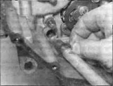
24 Note how the gearchange shaft centralising spring ends fit on each side of the locating pin in the crankcase and how the selector arm locates onto the pins on the stopper plate on the end of the selector drum. Grasp the end of the shaft and withdraw the shaft/arm assembly (see illustration). If the

|

|
|
20.16b... then fit the assembly...
20.18b... making sure it locates as shown
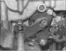
20.22 Note the alignment of the punch
marks (A) then remove the bolt (B) and
slide the arm off the shaft
20.18a Slide on the thrust washer and insert the shaft...

20.24 Draw the shaft/arm off the selector drum and out of the engine
Engine, clutch and transmission 2«37

|
Stopper arm bolt (A), stopper plate bolt (B)
20.30a Lever out the old seal.
20.30b... and press or drive in a new one
thrust washer doesn't come away with the shaft, retrieve it from the crankcase.
25 Note how the stopper arm spring ends locate and how the arm itself locates in the neutral detent on the stopper plate, then unscrew the stopper arm bolt and remove the arm and spring (see illustration).
26 If required, unscrew the belt securing the stopper plate to the selector drum and remove the plate (see illustration 20.25). Note the locating pin between the plate and the selector drum and remove it for safe keeping if required.
Inspection
27 Check the condition of the selector arm centralising spring and stopper arm return spring and renew them if they are cracked, weakened or distorted.
28 Check the selector arm for cracks, distortion and wear of its pawls, and check for any corresponding wear on the selector pins on the stopper plate. Also check the stopper arm roller and the stopper plate for any wear or damage, and make sure the roller turns freely. Renew any components that are worn or damaged.
29 Check that the centralising spring locating pin in the crankcase is securely tightened. If it is loose, remove it and apply a non-permanent thread locking compound to its threads, then tighten it to the torque setting specified at the beginning of the Chapter.
30 Check the gearchange shaft for
straightness and damage to the splines. If the
shaft is bent you can attempt to straighten it,
but if the splines are damaged the shaft must
be renewed. Also check the condition of the
shaft oil seal in the crankcase. If it is
damaged, deteriorated or shows signs of
leakage it must be renewed. Lever out the old
seal and press a new one squarely into place,
with its lip facing inward, using thumb
pressure, a seal driver or suitable socket (see
illustrations).
Installation
31 If removed, fit the stopper plate locating pin into the selector drum. Align the cutout in the back of the stopper plate with the locating pin and install the plate, then apply a suitable non-permanent thread locking compound to the bolt and tighten it securely.
32 Install the stopper arm return spring, washer, arm and bolt, locating the arm onto the neutral detent on the stopper plate, and tighten the bolt securely (see illustration). Make sure the spring is positioned correctly (see illustration 20.25).
33 Check that the gearchange shaft centralising spring is correctly positioned, then fit the thrust washer onto the end of the shaft (see illustration). Apply some grease to the lips of the gearchange shaft oil seal. Slide the shaft into place and push it all the way through the case until the splined end comes
out the other side, lifting the selector arm slightly as it is inserted and engage it with the pins on the stepper plate (see illustration 20.24). Make sure the centralising spring ends locate correctly on each side of the locating pin (see illustration). Remove the tape from the shaft splines.
34 Install the gearchange linkage arm onto the end of the shaft on the left-hand side of the engine, aligning the punch marks, and check that the mechanism works correctly (see illustrations 20.22) Tighten the pinch bolt.
35 Install the oil pump drive sprocket and chain, and the clutch (see Section 16).
| I |
21 Crankcase halves -
separation and reassembly
Note 1: To separate the crankcase halves, the engine must be removed from the frame. Note 2: If the cranfcases are being separated to inspect the crankshaft without removing it, or to remove the crankshaft without removing the connecting rods and pistons, or to inspect or remove the transmission shafts, the cylinder head can remain in situ. However, if removal of the connecting rod assemblies is Intended. full disassembly of the top-end is necessary. The gearchange mechanism external

|
Дата добавления: 2015-10-29; просмотров: 174 | Нарушение авторских прав
| <== предыдущая страница | | | следующая страница ==> |
| A Unscrew the bolt (arrowed)... 20.7b ... then remove the cam | | | Fit the arm, washer and spring onto |