|
Читайте также: |
(arrowed)...
3.5b... or at the connector (arrowed) if access is too restricted
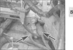
C On L, N and R models, disconnect the bullet connectors (arrowed)
good. If the spark appears thin or yellowish, or is non-existent, further invest gation will be necessary.
6 Ignition faults can be divided into two
categories, namely those where the ignition
system has failed completely, and those
which are due to a partial failure. The likely
faults are listed below, starting with the most
probable source of failure. Work through the
list systematically, referring to the subsequent
sections for full details of the necessary
checks and tests. Note: Before checking the
following items ensure that the battery is fully
charged and that all fuses are in good
condition.
a) Loose, corroded or damaged wiring connections, broken or shorted wiring between any of the component parts of the ignition system (see Chapter 9).
b) Faulty HT lead or spark plug cap, faulty spark plug, dirty, worn or corroded plug electrodes, or incorrect gap between electrodes.
c) Faulty ignition (main) switch or engine kill switch (see Chapter 9).
d) Faulty neutral, clutch or sidestand switch (L, N and R models only) (see Chapter 9).
e) Faulty pulse generator coil or damaged rotor.
f) Faulty ignition HT coilfs),
g) Faulty ignition control unit.
7 If the above checks don't reveal the cause
of the problem, have the ignition system
tested by a dealer equipped with the special diagnostic tester.
3 Ignition HT coils - check,
removal and installation ^;
Check
1 In order to determine conclusively that the ignition colls are defective, they should be tested by a dealer equipped with the special diagnostic tester.
2 However, the coils can be checked visually (for cracks and other damage) and the primary and secondary coil resistance can be measured with a multimeter. If the coils are undamaged, and if the resistance readings are as specified at the beginning of the Chapter, they are probably capable of proper operation.
3 On J and К models, remove the fuel tank (see Chapter 4). On L, N and R models, remove the fuel tank and the air filter housing (see Chapter 4). Disconnect the battery negative (-ve) lead on all models.
4 On J and К models, the coils are mounted under the frame cross-member behind the air filter housing, while on L, N and R models they are mounted on the frame under the front of the air filter housing.
5 Disconnect the primary circuit electrical connectors from the coil being tested and the
HT leads from the spark plugs. On J and К models, when testing the right-hand coil, it is easier to disconnect the two-pin connector in the bracket behind the air filter housing (black/white and blue/yellow wires) rather than disconnecting the wiring from the terminals on the coils (see illustrations). On L, N and R models, it is easie- to disconnect the bullet connectors in the primary circuit wiring on top of the coils rather than disconnecting the wiring from the terminals on the coils (see illustration). If testing the left-hand coil, disconnect the yellow/blue and black/white connectors. If testing the right-hand coil, disconnect the bite/yellow and black/white connectors. Mark the locations of all wires and leads before disconnecting them.
6 Set the meter to the ohms x 1 scale and measure the resistance between the primary circuit terminals (see illustration). This will give a resistance reading of the primary windings of the coi and should be consistent with the value given in the Specifications at the beginning of the Chapter.
7 To check the condition of the secondary windings, set the meter to the K-ohm scale. Connect one meter probe to one spark plug cap and the other probe to the other spark plug cap (see illustration). If the reading obtained is not within the range shown in the Specifications, disconnect the HT leads from the coils and repeat the measurement between the lead sockets in the coil (see illustration).

|
|

Дата добавления: 2015-10-29; просмотров: 135 | Нарушение авторских прав
| <== предыдущая страница | | | следующая страница ==> |
| Fairly difficult, | | | A Pulse generator coil wiring connector (arrowed) - J and К models |