Читайте также:
|
32.15a Fit a new gasket, locating it onto the dowels (arrowed)...
and the corresponding mating surface on the inside of the rotor with a suitable solvent. If removed, fit the Woodruff key into its slot in the crankshaft (see illustration). Make sure that no metal objects have attached themselves to the magnet on the inside of the rotor, then install the rotor onto the shaft. aligning the slot in the rotor with the Woodruff key (see illustration).
13 Install the rotor bolt and tighten it to the torque setting specified at the beginning of the Chapter, using the method employed on removal to prevent the rotor from turning (see illustrations).
14 If removed, apply some grease to the clutch release pushrod. then turn the shaft in the cover until the pushrod seat is aligned and insert the pushrod (see illustration).
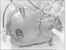
15 If removed, insert the dowels in the crankcase. Install the alternator/clutch cover using a new gasket, making sure it locates correctly onto the dowels, then install all the cover bolts with the exception of the two which secure the cable bracket (see illustrations). Tighten the bolts evenly in a criss-cross sequence to the specified torque setting.
16 Fit the clutch cable end into the release lever and position the bracket on the cover, then fit the two bolts and tighten them to the specified torque (see illustrations 32.6b and a).
17 Feed the alternator wiring back to its connector, making sure it is correctly routed. and reconnect it (see illustrations 32.2a and b). Install the fuel tank (see Chapter 4).
18 Refill the engine with oil (see Chapter 1).
19 Install the lower fairing (see Chapter 8).
33 Regulator/rectifier -
check and replacement SK
Check
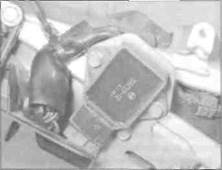
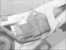
1 Remove the seat cowling (see Chapter 8). The regulator/rectifier is mounted on the left-hand side of the rear sub-frame on J and К models, and on the right on L, N and R models (see illustrations). On J and К models, disconnect the wiring connector. On L. N and R models, unscrew the two mounting bolts, then disconnect the wiring connector.
|
|
|
Дата добавления: 2015-10-29; просмотров: 134 | Нарушение авторских прав
| <== предыдущая страница | | | следующая страница ==> |
| Bulbs, with brightness varying considerably | | | B ... then install the cover |