Читайте также:
|
Check
29 See Chapter 3. Replacement - J and К models
30 Remove the instrument cluster (see Section 15).
31 Remove the screw securing each wiring connector, making a note of which fits where (see illustration).
32 Carefully pull the light bulbholder out of the back of the temperature gauge (see illustration 16.31).
33 Remove the two nuts and their washers securing the temperature gauge to the bracket and carefully withdraw the gauge from the front (see illustration 16.31).
34 Installation is the reverse of removal. Make sure the wires are correctly and securely connected.
Replacement - L, N and R models
35 Remove the instrument cluster (see
Section 15).
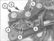
16.31 Remove the screws (A) and detach
the wires, then pull out the bulbholder (B)
and unscrew the nuts (C)
36 Using a very small Phillips screwdriver. remove the screw in the centre of the odometer trip knob and remove the knob (see illustrations 16.11).
37 Remove the screws securing the instrument cluster front cover, noting the positions of the wi'ing clips, and remove the cover (see illustration 16.12).
38 Remove the screw securing each wiring connector, making a note of which fits where. then carefully withdraw the temperature gauge from the fronl (see illustration).
39 Installation is the reverse of removal. Make sure the wires are correctly and securely connected.
17 Instrument and warning light |b>
bulbs - renewal Ц;

|
1 Remove the fairing (see Chapter 8).
2 Some of the bulbs are accessible with the instrument cluster in place, but access to others is quite restricted. If it Is too restricted for the bulb you are changing, displace the instrument cluster (see Section 15) to improve
9*14 Electrical system

|
access - there is no need to disconnect any of the wiring connectors, though it may be necessary to disconnect the speedometer cable, depending on which bub Is being renewed.
3 Gently pull the bulbholder out of the back of the instrument casing, then pull the bulb out of the bulbholder (see illustrations).
4 If the socket contacts are dirty or corroded. scrape them clean and spray with electrical contact cleaner before a new bulb is installed.
5 Carefully push the new bulb into the holder, then push the holder into the easing.
6 Install the fairing (see Chapter 8).
17.3a Pull out the bulbholder...
17.3b... and remove the bulb
18 Oil pressure switch - check, |g>
removal and installation ^
Check
1 The oil pressure warning light should come on when the ignition (main) switch is turned ON and extinguish a few seconds after the engine is started. If the oil pressure warning light comes on whilst the engine is running. stop the engine immediately and carry out an oil level check (see Daily (pre-ride) checks), and if the level is correct, an Oil pressure check (see Chapter 1).
2 If the oil pressure warning light does not come on when the ignition is turned on, check the bulb (see Section 17) and tall/signal fuse (see Section 5).
3 The oil pressure switch is screwed into the crankcase behind the cylinders and is accessed by removing the fuel tank and the carburettors (see Chapter 4). Pull the rubber cover off the switch and remove the screw securing the wiring connector (see illustrations). With the ignition switched ON, earth (ground) the wire on the crankcase and check that the warning light comes on. If the light comes on, the switch is defective and must be renewed.
4 If the light still does not come on, check for voltage at the wire terminal. If there is no voltage present, check the wire between the switch, the instrument cluster and tail/signal
fuse for continuity (see the wiring diagrams at the end of this Chapter).
5 If the warning light comes on whilst the
engine is running, yet the oil pressure is
satisfactory, remove the wire from the oil
pressure switch. With the wire detached and
the ignition switched ON the light should be
out. If it is Illuminated, the wire between the
switch and instrument cluster must be
earthed (grounded) at some point. If the wiring
is good, the switch must be assumed faulty
and renewed.
Removal
6 Remove the fuel tank and the carburettors (see Chapter 4).
7 Pull the rubber cover off the switch and remove the screw securing the wiring connector (see illustrations 18.3a and b).
8 Unscrew the oil pressure switch and withdraw It from the crankcase.
Installation
9 Apply a suitable sealant to the upper
portion of the switch threads near the switch
body, leaving the bottom 3 to 4 mm of thread
clean. Install the switch in the crankcase ana
tighten it to the torque setting specified at the
beginning of the Chapter.
10 Attach the wiring connector and secure it with the screw, then fit the rubber cover (see illustrations 18.3b and a).
11 Install the carburettors and fuel tank (see Chapter 4). Run the engine and check that the switch operates correctly.
19 Ignition (main) switch -
check, removal and installation *4
| A |
Warning: To prevent the risk of short circuits, remove the rider's seat (see Chapter 8) and disconnect the battery negative (-ve) lead before making any ignition (main) switch checks.
Check
1 Remove the fairing Jsee Chapter 8). Trace the ignition (main) switch wiring back from the base of the switch and disconnect it at the black connector. On J and К models, the connector is on the right-hand end of the bracket above the headlights. On L N and R models, the connector is in the bracket on the left-hand side of the bike (see illustration).
2 Using an ohmmeter or a continuity tester, check the continuity of the connector terminal pairs (see the wiring diagrams at the end of this Chapter). Insert the key in the switch. Continuity should exist between the terminals connected by a solic line on the diagram when the switch is in the indicated position.
3 If the switch fails any of the tests, renew it.
Removal
4 Remove the fairing;see Chapter 8). Trace
the ignition (main) switch wiring back from the
base of the switch and disconnect it at the
black connector. On J and К models, the

|
18.3a Pull back the rubber cover.
18.3b... then remove the terminal screw and detach the wiring
19.1 Ignition switch wiring connector (arrowed) - L, N and R models
Electrical system 9*15

|
| Ту | (в) Щ | ||
| -■-'^-•i |
| 19.5 Access the bolts from the underside of the switch (arrowed) |
20.3 Right-hand switch wiring
connector (A), left-hand switch wiring
connectors (B) - L, N and R models
| connector is on the right-hand end of the bracket above the headlights. On L, N and R models, the connector is in the bracket on the left-hand side of the bike (see illustration 19.1). Draw the wiring through to the switch. releasing it from any clips or ties and noting its routing. 5 Two Torx bolts mount the ignition switch to the underside of the top yoke (see illustration). Ease of access to these bolts depends on the tools available. It may be necessary to either displace or remove the instrument cluster (see Section 15), or to displace the top yoke (see Chapter 6). 6 Remove the bolts and withcraw the switch from the top yoke. Installation 7 Installation is the reverse of removal. Tighten the Torx bolts to the torque setting specified at the beginning of the Chapter. Make sure the wiring is securely connected and correctly routed. |
internal parts is a possibility that should not be overlooked. If breakage does occur, the entire switch and related wiring harness will have to be renewed as individual parts are not available.
| 20 Handlebar switches - check |
| | |
| 1 Generally speaking, the switches are reliable and trouble-free. Most troubles, when they do occur, are caused by dirty or corroded contacts, but wear and breakage of |

|
2 The switches can be checked for continuity using an ohmmeter or a continuity test light. Always disconnect the battery negative (-ve) lead, which will prevent the possibility of a short circuit, before making the checks.
3 Remove the fairing (see Chapter 8). Trace the wiring harness of the switch in question back to its connector(s) and disconnect it/them. On J and К models, the right-hand switch connector is the red one in the bracket above the headlight, and the left-hand switch connectors (one black, one white) are on the left-hand end of the bracket. On L, N and R models, the connectors are in the bracket on the left-hand side of the bike (see illustration).
4 Check for continuity between the terminals of the switch harness with the switch in the various positions (ie switch off - no continuity, switch on - continuity) - see the wiring diagrams at the end of this Chapter.
5 If the continuity check indicates a problem exists, refer to Section 21, remove the switch and spray the switch contacts with electrical contact cleaner. If they are accessible, the contacts can be scraped clean with a knife or polished with crocus cloth. If switch components are damaged or broken, it will be obvious when the switch is disassembled.
| i -j | ||
| с | I M ^- | |
| ^ ' | * | ж^л |
| / ; | m | I^M ^Ъ ^^W1* |
21.3a Right-hand switch screws (arrowed) 21.3b Left-hand switch screws (arrowed)
21 Handlebar switches-
removal and installation
ч ^
Removal
1 If the switch is to be removed from the bike, rather than |ust displaced from the handlebar. remove the fairing (see Chapter 8), then trace the wiring harness of the switch in question back to its connector(s) and disconnect it/them. On J and К models, the right-hand switch connector is the red one in the bracket above the headlight, and Ihe left-hand switch connectors (one black, one white) are on the left-hand end of the bracket. On L, N and R models, the connectors are in the bracket on the left-hand side of the bike (see illustration 20.3). Work back along the harness, freeing it from all the relevant clips and lies, noting its correct routing.
2 Disconnect the two wires from the front brake light switch (if removing the right-hand switch) or the clutch switch (If removing the left-hand switch) (see illustration 14.5 or 24.2).
3 Unscrew the two handlebar switch screws and free the switch from the handlebar by separating the halves (see illustrations).
Installation
4 Installation is the reverse of removal. Make
sure the locating pin in the lower half of the
switch locates in the hole in the underside of
the handlebar.
22 Neutral switch - check, removal and installation
Check
1 Before checking the electrical circuit, check the bulb (see Section 17) and fuse (see Section 5).
2 The switch is located in the left-hand side of the engine below the front sprocket cover. On J and К models remove the lower fairing (see Chapter 8). On L. N and R models the fairing does not restrict access, but removing it gives more room. Make sure the transmission is in neutral. Detach the wiring connector from the switch (see illustration overleaf).
3 With the connector disconnected and the ignition switched ON, the neutral light should be out. If not. the wire between the connector and instrument cluster must be earthed (grounded) at some point.
4 Check for continuity between the switch terminal and the crankcase. With the transmission in neutral, there should be continuity. With the transmission in gear, there should be no continuity. If the tests prove otherwise, then the switch is faulty. Q
5 If the continuity tests prove the switch is
9» 16 Electrical system

22.2 Disconnect the wiring connector from the neutral switch
good, check for voltage at the wire terminal using a test light. If there's no voltage present, check the wire between the switch, instrument cluster and fusebox (see the wiring diagrams at the end of this Chapter).
6 On L. N and R models note that a diode is
located in the power supply from the
instrument cluster to the switch (see Sec
tion 25), Trace the light green wire from the
switch up to the diode. Disconnect the diode
from the wiring harness. Using an ohmmeter
or continuity tester connect its probes
between the light green and light green/red
wire terminals on the diode, then reverse the
probes. Continuity should only exist in
one direction (as indicated on the body
of the diode). If the diode shows the same
condition in each direction it should be
renewed.
Removal
7 The switch is located in the left-hand side of the engine below the front sprocket cover. On J and К models remove the lower fairing (see Chapter 8). On L, N and R models the fairing does not restrict access, but removing it gives more room.
8 Detach the wiring connector from the switch (see illustration 22^).
9 Unscrew the switch and withdraw it from the transmission casing.
Installation
10 Apply a smear of sealant to the threads of
23.2 Sidestand switch wiring connector (arrowed)
the switch, taking care not to cover the contact point.
11 Install the switch and tighten it to the torque setting specified at the beginning of the Chapter.
12 Check the operation of the neutral light.
13 Install the lower fairing (see Chapter 8).
23 Sidestand switch (L, N and R ^
models) - check and Л»
replacement iS
Check
1 The sidestand switch is mounted on the back of the sidestand. The switch is part of the safety circuit which prevents or stops the engine running if the transmission is in gear whilst the sidestand is down, and prevents the engine from starting if the transmission is in gear unless the sidestand is up. and unless the clutch is pulled in. Before checking the electrical circuit. check the warning bulb (see Section 17) and the tail/3ignal fuse (see Section 5).
2 Remove the fuel tank (see Chapter 4). Trace the wiring back from the switch to its connector and disconnect it (see illustration). Place the bike on an auxiliary stand or have an assistant hold it upright whilst the checks are made.
3 Check the operation of the switch using an ohmmeter or continuity test light. Connect the meter to the green/white and green wires on
the switch side of the connector. With the sidestand up there shauld be continuity (zero resistance) between the terminals, and with the stand down there should be no continuity (infinite resistance). Now connect the meter to the yellow/black and green wires on the switch side of the connector. With the sidestand down there should be continuity (zero resistance) between the terminals, and with the stand up there should be no continuity (infinite resistance).
4 If the switch does not perform as expected, it is defective and must be renewed.
5 If the switch is good, check the wiring between the various components in the starter safety circuit (see the wiring diagrams at the end of this book).
Replacement
6 The sidestand switch is mounted on the back of the sidestard (see illustration). Remove the lower fairing (see Chapter 8) and the fuel tank (see Chapter 4), Trace the wiring back from the switch to its connector and disconnect it (see illustration 23.2). Work back along the switch wiring, freeing it from any relevant retaining clips and ties, noting its correct routing.
7 Unscrew the switch bolt and remove the switch from the stand, noting how it fits.
8 Fit the new switch onto the sidestand, making sure the pin locates in the hole in the sidestand. and the lug for the spring on the stand bracket locates into the cutout in the switch body (see illustration 23.6). Tighten the bolt to the torque setting specified at the beginning of the Chapter.
9 Make sure the wiring Is correctly routed up to the connector and retained by all the necessary clips and ties.
10 Reconnect the wiring connector and check the operation of the sidestand switch.
11 Install the fuel tank (see Chapter 4) and the lower fairing (see Chapter 8).
24 Clutch switch -
check and replac

|

23.6 The sidestand switch bolt is on the inside (A). Note how the lug locates (B)
24.2 Clutch switch wiring connectors
Check
1 The clutch switch is housed in the clutch lever bracket. On J and К models the clutch switch prevents the engine from being started whilst in gear unless the clutch lever is pulled in. On L, N and R models the clutch switch prevents the engine from being started unless the clutch lever is pulled in and the sidestand Is up.
2 To check the switch, disconnect the wiring connectors from the switch (see illustration). Connect the probes of an ohmmeter or a continuity test light to the two switch terminals. With the clutch lever pulled in,
Electrical system 9«17
continuity should be indicated. With the clutch lever out, no continuity (infinite resistance) should be indicated. Reconnect the wiring connectors.
3 If the switch is good, check for voltage at
one of the terminals on the clutch switch
Wiring connectors with the ignition ON - there
will be battery voltage on one terminal and
zero on the other. If voltage is indicated,
check the other components in the starter
circuit as described in the relevant sections of
this Chapter. If no voltage is indicated, or if all
components are good, check the wiring
between the various components (see the
wiring diagrams at the end of this book).
Replacement
4 Remove the clutch lever (see Chapter 6).
5 Disconnect the wiring connectors from the clutch switch (see illustration 24.2), Using a small screwdriver, push the switch from the connector end and withdraw it from inside the bracket.
6 Installation is the reverse of removal. Make sure the ridge on the top of the switch locates in the cutout in the lever bracket, and push the switch fully home.
25 Diode -
check and replacement |k
Check
1 Remove the fuel tank (see Chapter 4).
2 The diode is a small block that plugs into a connector in the main wiring harness (see illustration). The diode is part of the safety circuit which prevents or stops the engine running if the transmission is in gear whilst the sidestand is down, and prevents the engine from starting if the transmission is in gear unless the sidestand is up and the clutch lever is pulled in.
3 Disconnect the diode from the harness (see illustration 25.2).
4 On J and К models (two-pin diode), using an ohmmeter or continuity tester, connect its probes between the two terminals on the diode, then reverse the probes. The diode should only show continuity in one direction (as indicated by the symbol on the body of the diode). If the diode shows continuity or no continuity in both directions it should be renewed.
5 On L. N and R models (three-pin diode), using an ohmmeter or cortinuity tester, connect one probe to one of the outer terminals of the diode and the other probe to the middle terminal of the diode (the terminal which connects to the light green wire in the wire harness). Now reverse the probes. The diode should only show continuity in one direction (as indicated by the symbol on the body of the diode). If the diode shows continuity or no continuity in both directions it should be renewed. Repeat the tests between

25.2 Diode (arrowed) - J and К models
the other outer terminal and the middle terminal. The same results should be achieved. If It doesn't behave as stated, renew the diode.
6 If the diode is good, check the other
components in the starter circuit as described
in the relevant sections of this Chapter. If all
components are good, check the wiring
between the various components (see the
wiring diagrams at the end of this book).
Replacement
7 Remove the fuel tank (see Chapter 4).
8 The diode is a small block that plugs Into a connector in the main wiring harness (see illustration 25.2). Disconnect the diode from the harness and connect the new one.
26 Horn -
check and replacement ^,
Check

|
| 27.2 Starter relay - J and К models shown |
1 The horn is mounted on the underside of the bottom yoke. If required, remove the fairing for improved access (see Chapter 8).
2 Disconnect the wiring connectors from the horn (see illustration 26.5). Using two jumper wires, apply battery voltage directly to the terminals on the horn. If the horn sounds. check the switch (see Section 21) and the wiring between the switch and the horn (see the wiring diagrams at the end of this Chapter).
3 If the horn doesn't sound, renew It.

26.5 Disconnect the wiring connectors (A), then unscrew the bolt (B)
Replacement
4 The horn is mounted on the underside of the bottom yoke. If required, remove the fairing for improved access (see Chapter 8).
5 Disconnect the wiring connectors from the horn, then unscrew the bolt securing the horn and remove it from the bike (see illustration).
6 Install the horn and securely tighten the bolt. Connect the wiring connectors to the horn.
27 Starter relay -
check and replacement ^»
Check
1 If the starter circuit is faulty, first check the main fuse and ignition/starter fuse (see Section 5).
2 Remove the seat cowling (see Chapter 8). The starter relay is located behind the seat cowling on the right-hand side of the bike on J and К models, and on the left on L. N and R models (see illustration).
3 Disconnect the relay wiring connector to provide access to the rear terminals, then lift the rubber terminal cover and unscrew the bolt securing the starter motor lead (see illustrations); position the lead well away from the relay terminal. Reconnect the wiring connector. With the ignition switch ON. the engine kill switch in the RUN position, the transmission in neutral and the clutch pulled

9»18 Electrical system
27.3b... then trace the lead from the
starter motor and detach it from the relay
by removing its bolt
in. press the starter switch. The relay should be heard to click.
4 If the relay doesn't click, switch off the ignition and remove the relay as described below; test it as follows.
5 Set a multimeter to the ohms x 1 scale and connect il across the relay's starter motor and battery lead terminals (see illustration 27.3b). Using a fully-charged 12 volt battery and I wo insulated jumper wires, connect the positive (+ve) terminal of the battery to the yellow/red wire terminal of the relay, and the negative (-ve) terminal to the green/red wire terminal of the relay. At this point the relay should be heard to click and the multimeter read 0 ohms (continuity). If this is the case the relay is proved good. If the relay does not click when battery voltage is applied and indicates no continuity (infinite resistance) across its terminals, it is faulty and must be renewed.
6 If the relay is good, check for battery voltage between the yellow/red wire and the green/red wire when the starter button is pressed. Check the other components in the starter circuit as described in the relevant sections of this Chapter. If all components are good, check the wiring between the various components (see the wiring diagrams at the end of this book).
Replacement
7 Remove the seat cowling (see Chapter 8),
The starter relay is located behind the seat
cowling on the right-hand side of the bike on J
28.3 Pull back the cover, unscrew the nut and detach the lead
and К models, and on the left on L, N and R models (see illustration 27.2).
8 Disconnect the battery terminals, remembering to disconnect the negative (-ve) terminal first.
9 Disconnect the relay wiring connector, then unscrew the two bolts securing the starter motor and battery leads to the relay and detach the leads (see illustrations 27.3a and b). Remove the relay with its rubber sleeve from its mounting lug on the frame.
10 Installation is the reverse of removal.
Make sure the terminal nuts are securely
tightened. Connect the negative (-ve) lead last
when reconnecting the battery.
28 Starter motor -
removal and installation
Removal
1 Remove the rider's seat (see Chapter 8). Disconnect the battery negative (-ve) lead. The starter motor is mounted on the crankcase behind the cylinder block.
2 On J and К models, remove the carburettors (see Chapter 4). On L. N and R models, either remove the carburettors or displace the fuel pump according to preference and the tools available for accessing the starter motor bolts (see Chapter 4).
28.4 Unscrew the two bolts (arrowed), noting the lead
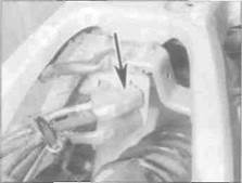
3 Peel back the rubber terminal cover, then remove the nut securing the starter lead to the motor and detach the lead (see illustration).
4 Unscrew the two bolts securing the starter motor to the crankcase, noting the earth lead attached to the front bolt (see illustration). Slide the starter motor out from the crankcase and remove it from the machine (see illustration 28.7a).
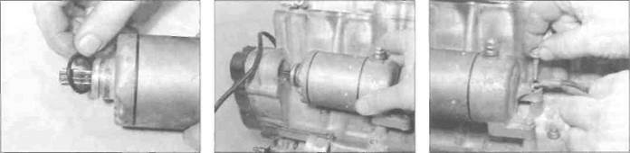
5 Remove the O-ring on the end of the starter motor and discard it as a new one must be used (see illustration 28.6).
Installation
6 Install a new O-ring on the end of the starter motor and ensure it is seated in its groove (see illustration). Apply a smear of engine oil to the O-ring to aid installation.
7 Manoeuvre the motor into position and slide it into the crankcase (see illustration). Ensure that the starter motor teeth mesh correctly with these of the starter idle/reduction gear. Install the mounting bolts, not forgetting to fit the earth lead with the front bolt, and tighten them securely (see illustration).
8 Connect the starter lead to the motor and secure it with the nut (see illustration 28.3). Make sure the rubber cover is correctly seated over the terminal.
9 Connect the battery negative (-ve) lead and install the carburettors or fuel pump and the rider's seat.
|
28.6 Fit a new O-ring
28.7a... then install the starter motor
28.7b Do not forget to secure the earth lead with the front bolt
Electrical system 9» 19

|
Дата добавления: 2015-10-29; просмотров: 142 | Нарушение авторских прав
| <== предыдущая страница | | | следующая страница ==> |
| Replacement - L, N and R models | | | Note the alignment marks between the housing and the covers (arrowed) |