Читайте также:
|
6 Remove the fairing (see Chapter 8).
7 Unscrew the knurled ring securing the speedometer cable to the back of the speedometer and detach the cable (see illustration 15.12).
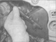
8 Pull back the rubber boot above the headlight and disconnect the two black wiring connectors (see illustration).
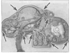
9 Unscrew the two bolts securing the instrument cluster and carefully remove it (see illustration). Note how the two pegs locate in


15.9a... then unscrew the bolts (arrowed)...
the rubber gromrrets In the bracket (see
Illustration).
Installation - ail models
10 Installation is the reverse of removal.
Make sure that the speedometer cable and
wiring connectors are correctly routed and
secured.
Speedometer cable
Removal
11 Remove the fairing (see Chapter 8).
12 Unscrew the knurled ring securing the speedometer cable to the back of the speedometer and detach the cable (see illustration).
13 Remove the screw securing the lower end of the cable to the drive housing on the front sprocket cover and detach the cable (see illustration).

B... and remove the cluster, noting how it locates (arrowed)
Unscrew the ring (arrowed) and detach the cable
Remove the screw (arrowed) and detach the cable
Electrical system

|
|

|
Fit the upper end into the speedometer and tighten the ring
Fit the lower end into the drive housing and tighten the screw
Remove the screw (A), disconnect
The wiring connectors (B), then unscrew
The nuts (C)
|
14 Withdraw the cable, releasing it from its
guides, and remove it from the bike, noting its
correct routing.
Installation
15 Route the cable up through its guides to the back of the instrument cluster.
16 Connect the cable upper end to the speedometer and tighten the retaining ring securely (see illustration).
17 Connect the cable lower end to the drive housing and tighten the retaining screw securely (see illustration).
18 Check that the cable doesn't restrict steering movement or interfere with any other components, then install the "airing (see Chapter 8).
16 Instruments -
check and replacement
Speedometer
Check
1 Special Instruments are required to properly
check the operation of this meter. If it is
believed to be faulty, take the speedometer to
a dealer for assessment.
Дата добавления: 2015-10-29; просмотров: 125 | Нарушение авторских прав
| <== предыдущая страница | | | следующая страница ==> |
| L, N and R models | | | Replacement - L, N and R models |