with engine speed, and battery
Overheating.
| I |
32 Alternator - check, removal and installation
Check
1 Remove the fuel tank (see Chapter 4).
2 Trace the wiring back from the top of the alternator/clutch cover on the right-hand side of the engine and disconnect it at the white (J and К models) or red (L, N and R models) connector containing the three yellow wires (see illustrations).

|

|
AMMETER

31.3 Checking the charging system leakage rate - connect the meter as shown
32.2a Alternator wiring connector (arrowed) - J and К models
32.2b Alternator wiring connector (arrowed) - L, N and R models
Electrical system 9#23
|
| 32.6a Remove the bracket bolts (arrowed)... |

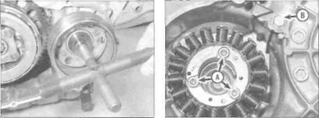
Unscrew the rotor bolt using a strap as shown, if available
3 Using a multimeter set to the ohms x 1 (ohmmeter) scale measure the resistance between each of the yellow wires on the alternator side of the connector, taking a total of three readings, then check for continuity between each terminal and ground (earth). If the stator coil windings are in good condition the three readings should be within the range shown in the Specifications at the start of this

A rotor holding tool can easily be made using two strips of steel bolted together in the middle, and with a bolt through each end which locate into the recessed bores in the rotor.
B... and free the cable end from the lever
Chapter and there should be no continuity (infinite resistance) between any of the terminals and earth. If not, the alternator stator coil assembly is at fault and should be renewed. Note: Before condemning the stator coils, check the fault is not due to damaged wiring between the connector and coils.
Removal
| 32.9 Remove the rotor using a puller as shown |
4 Remove the lower fairing (see Chapter 8) and the fuel tank (see Chapter 4). Trace the alternator wiring from the alternator/clutch cover and disconnect it at the white (J and К models) or red (L. N and R models) connector containing the three yellow wires (see illustrations 32.2a and b). Free the wiring from any clips or guides and feed it through to the alternator/clutch cover.
5 Drain the engine oil (see Chapter 1).
6 Unscrew the two bolts securing the clutch cable bracket to the alternator/clutch cover on the right-hand side of the engine, then free the cable end from the release lever (see illustrations). Position the cable clear of the engine.
7 Unscrew the remaining alternator/clutch cover bolts and remove the cover, being prepared to catch any residue oil (see illustration). Discard the gasket as a new one must be used. Remove the dowels from either the cover or the crankcase if they are loose, Note the pushrod fitted in the bottom of the shaft in the cover and remove it for safekeeping if required (see illustration 32.14). It is possible that it is stuck to the
Дата добавления: 2015-10-29; просмотров: 166 | Нарушение авторских прав
| <== предыдущая страница | | | следующая страница ==> |
| Note the alignment marks between the housing and the covers (arrowed) | | | Fit the clutch pushrod if removed |