Читайте также:
|
1 Since no provision exists for adjusting the ignition timing and since no component is subject to mechanical wear, there is no need for regular checks; only if investigating a fault such as a loss of power or a misfire, should the ignition timing be checked.
2 The ignition timing is checked dynamically (engine running) using a stroboscopic lamp. The inexpensive neon lamps should be adequate in theory, but in practice may produce a pulse of such low intensity that the timing mark remains Indistinct. If possible, one of the more precise xenon tube lamps

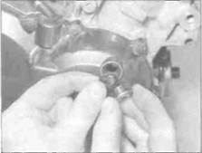
On J and К models, the wiring
Connectors are inside the rubber boot -
Trace the wiring from the unit and
Disconnect the relevant ones
should be used, powered by an external source of the appropriate voltage. Note: Do not use the machine's own battery as an incorrect reading may result from stray impulses within the machine's electrical system.
Check
| 6.4 Unscrew the timing inspection plug (arrowed) |
3 Warm the engine up to normal operating temperature then stop it.
4 Unscrew the timing inspection plug from the alternator cover on the right-hand side of the engine (see illustration). Discard the cover O-ring as a new one must be used.
5 The timing mark on the alternator rotor which indicates the firing point at idle speed for cylinders nos. 1 and 4 is a line with the
5»6 Ignition system

|
6.11 Install the plug using a new O-ring
letter F next to it. The static timing mark with which this should align is the notch in the timing inspection plug hole.
РТТНтЗЯ The timing marks can be ll.iUkiTl nignugnted With white paint Hi All to make them more visible ~ under the stroboscope light.
6 Connect the timing light to the no. 4 cylinder HT lead as described in the manufacturer's instructions.
7 Start the engine and aim the light at the static timing mark.
8 With the machine idling at the specified speed, the line next to the timing mark F should align with the static timing mark.
9 Slowly increase the engine speed whilst observing the timing mark. The timing mark should move anti-clockwise, increasing in relation to the engine speed until It reaches full advance (no identification mark).
| 7.2 Disconnect the throttleposition sensor wiringconnector |
10 As already stated, there is no means of
adjusting the ignition timing on these
machines. If the ignition timing is incorrect, or
suspected of being incurred, one uf the
ignition system components is at fault, and the system must be tested as described in the preceding Sections of this Chapter. 11 When the check is complete, install the timing inspection plug using a new O-ring and smear it and the cover threads with molybdenum disulphide oil (a 50/50 mixture of molybdenum disulphide grease and engine oil) (see illustration).
7 Throttle position sensor -
| I |
check and replacement
Check
| 7.11Remove thesensor mountingplate screws (arrowed) and remove thesensor |
1 The throttle position sensor is fitted to the carburettors on L, N and R models only. Remove the fuel tank (see Chapter 4) and the right-hand rear trim panel (see Chapter 8).
2 The throttle sensor is mounted on the outside of the right-hand (no. 4) carburettor. Disconnect the wiring connector from the sensor (see illustration). Check the sensor visually for cracks and other damage.
3 Arrange a temporary fuel supply, either by using a small temporary tank or by using extra long fuel hoses to the now remote fuel tank on a nearby bench. Whichever method is used, connect the fuel supply hose to the inlet union on the in-line filter - do not connect it directly to the carburettors or you will by-pass the fuel pump.
4 Start the engine and increase speed to 3000 to 3500 rpm. Now connect the sensor wiring connector - as it is connected, the engine speed should rise. Stop the engine and turn the ignition OFF.
5 If the engine speed does not rise. disconnect the wring connector. Using a multi-meter set to the ohms x 10 scale, measure the resistance between the
green/black and yellow/black terminals on the wiring loom side of the connector. A reading of 4 to 6 ohms should be recorded. Now set the meter to the dc volts scale and measure the voltage between the green/black and yellow/black terminals on the wiring loom side of the connector with the ignition switched ON. A reading of 5 volts should be recorded.
6 If the above readings are not as specified, disconnect the ignition control unit wiring connector (see Section 5). Check the sensor and control unit connectors for loose or corroded terminals. Using a multimeter set on the ohms range or a continuity tester, check the three wires which run from the throttle sensor connector to the ignition control unit connector for continjity. There should be continuity from one end of the wire to the other. If not, this is probably due to a damaged or broken wire between the connectors; pinched or broken wires can usually be repaired.
7 If the readings taken in Step 5 are as specified, disconnect the sensor wiring connector. Using a multimeter set on the ohms range, measure the resistance between each pair of terminals on the sensor in turn as the throttle is opened and closed. As the throttle is opened, the resistance should increase. As the throttle is closed, the resistance should decrease. If the readings obtained are not as specified, the sensor is faulty and should be renewed; the sensor is a sealed unit and cannol therefore be repaired.
8 If the readings taken are as specified, and the wiring is all good, it is possible that the ignition control unit is faulty.
9 II you are in doubt as to the results obtained, take the sensor to a dealer for testing.
Replacement
10 Remove the fuel tank (see Chapter 4) and the right-hand rear trim panel (see Chapter 8). Depending on the tools available, it may also be necessary to displace the carburettors to access the mounting plate screws (see Chapter 4).
11 The throttle sensor is mounted on the outside of the right-hand (no. 4) carburettor. Unscrew the sensor mounting plate screws and remove the sensor, noting how it fits (see illustration). Do not separate the sensor from its mounting plate as its position has been pre-set.
12 Install the sensor, aligning the tab with the slot on the end of the throttle shaft, and tighten the mounting plate screws securely.
13 Install the carburettors (see Chapter 4).
6*1
Chapter 6
Frame, suspension and final drive
Contents
Drive chain - removal, cleaning and installation......................... 15
Drive chain and sprockets - check, adjustment
and lubrication............................................................ see Chapter 1
Footrests, brake pedal and gearchange lever -
removal and installation............................................................. 3
Forks - disassembly, inspection and reassembly....................... 7
Forks - oil change........................................................ see Chapter 1
Forks - removal and installation.................................................... 6
Frame - inspection and repair....................................................... 2
General information........................................................................ 1
Handlebars and levers - removal and Installation....................... 5
Handlebar switches - check........................................ see Chapter 9
Handlebar switches - removal and installation........... see Chapter 9
Rear shock absorber - removal, inspection and installation... 10
Rear suspension linkage - removal, inspection and Installation.... 11
Sidestand - check.......................................................... see Chapter 1
Sidestand - lubrication................................................ see Chapter 1
Sidestand - removal and installation.......................................... 4
Sidestand switch - check and replacement............... see Chapter 9
Sprockets - check and renewal.................................................... 16
Sprocket coupling/rubber damper - check and renewal............ 17
Steering head bearings - freeplay check and
adjustment................................................................... see Chapter 1
Steering head bearings - inspection and renewal..................... 9
Steering head bearings - lubrication............................ see Chapter 1
Steering stem - removal and Installation.................................... 8
Suspension - adjustments............................................................ 12
Suspension - check....................................................... see Chapter 1
Swingarm - inspection and bearing renewal.............................. 14
Swingarm - removal and installation.......................................... 13
Swingarm and suspension linkage bearings -
lubrication.................................................................... see Chapter 1
Degrees of difficulty
Easy, suitable for novice with little experience
;=>■
*
Fairly easy, suitable |k
for beginner with
some experience 2S
Fairty difficult, ^,
suitable for competent ^
DIY mechanic !^S
Difficult, suitable for |k
experienced DIY ^
mechanic JS
Дата добавления: 2015-10-29; просмотров: 136 | Нарушение авторских прав
| <== предыдущая страница | | | следующая страница ==> |
| B ... then install the cover | | | Very drfficurt, |