Читайте также:
|

|
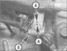
| 15.8 Check that the ends of the joining link are properly staked |
5 Remove the sleeve (J and К models) or
collar (L, N, and R models) from the left-hand
side of the swingarm (see illustration 14.1).
Lever out the seals from each side, taking
care not to damage them, and remove the
circlip from the right-hand side. Refer to Tools
and Workshop Tips (Section 5) in the
Reference section and remove the bearings,
then clean them and inspect them for wear or
damage. A needle bearing is fitted in the left-
hand side, and two ball bearings are in the
right-hand side. If the bearings do not run
smoothly and freely or if there is excessive
freeplay, they must be renewed. The needle
bearing in the left-hand side of the swingarm
should be renewed as a matter of course If it
is removed.
6 Do not forget to install the bearing spacer between the bearings in the swingarm. When installing the new needle bearing, lubricate it with molybdenum disulphide grease and set it in the swingarm to a depth of exactly 4 mm. Check the condition of the dust seals and renew them if they are damaged or deteriorated.
15 Drive chain - removal, cleaning and installation
Removal
Note: The original equipment drive chain fitted
to these models has a staked-type master
(joining) link which can be disassembled using
either Honda service tool, Pt. No. 07HMH-
MR10100 for J and К models, 07HMH-
MR10101 for L and N models or 07HMH-
MR10102 for R models, or one of several
commercially-available drive chain
cutting/staking tools. Such chains can be recognised by the master link side plate's identification marks (and usually its different colour), as well as by the staked ends of the link's two pins which look as if they have been deeply centre-punched, instead of peened over as with all the other pins.
| A |
Warning: NEVER install a drive chain which uses a clip-type master (split) link. Use ONLY the correct service tools to secure the staked-type of master link - if you do not have access to such tools, have the chain renewed by a dealer to be sure of having it securely installed.
1 Locate the joining link in a suitable position to work on by rotating the back wheel.
2 Slacken the drive chain as described in Chapter 1.
3 Split the chain at the joining link using the chain cutter, following carefully the manufacturer's operating instructions (see also Section 8 in Tools and Workshop Tips in the Reference Section). Remove the chain from the bike, noting its routing through the swingarm.
Cleaning
4 Soak the chain in kerosene (paraffin) for
approximately five or six minutes.
Caution: Don't use gasoline (petrol),
solvent or other cleaning fluids which
might damage its internal sealing
properties. Don't use high-pressure water.
Remove the chain, wipe it off, then blow
dry it with compressed air immediately.
The entire process shouldn't take longer
than ten minutes - if it does, the O-rings in
the chain rollers could be damaged.
Installation
A Warning: If you do not have access to a chain riveting tool, have the chain fitted by a dealer.
5 Unscrew the gearchange lever linkage arm pinch bolt and remove the arm from the shaft, noting the alignment punch marks (see illustration 16.1a). If no marks are visible, make your own be'ore removing the arm so that it can be correctly aligned with the shaft on installation. If required, detach the speedometer cable from the front sprocket cover. Unscrew the bolts securing the sprocket cover and remove it, noting the guide plate (see illustration 16.1b). Let the cover hang by the cable, if it wasn't detached. On L, N and R models, note the wiring clip secured by the lower bolt.
6 Install the drive chain through the swingarm sections and around the front sprocket, leaving the two ends in a convenient position to work on.
7 Refer to Section 8 in Tools and Workshop Tips in the Reference Section. Install the new joining link from the inside with the four O-rings correctly located between the link plates. Install the new side plate with its identification marks facing out. On R models, measure the amount that the joining link pins project from the side plate and check they are within the measurements specified at the beginning of the Chapter. Stake the new link using the drive chain cutting/staking tool, following carefully the instructions of both the chain manufacturer and the tool manufacturer. DO NOT re-use old joining link components.
8 After staking, check the joining link and staking for any signs of cracking (see illustration). If there is any evidence of cracking, the joining link. O-rings and side plate must be renewed. On R models, measure the diameter of the staked ends in two directions and check that it is evenly staked and within the measurements specified at the beginning of the Chapter.
9 Install the sprocket cover with its guide plate, making sure the speedometer cable drive socket on the inside of the cover engages correctly with the head of the sprocket bolt. On L, N and R model, do not forget the wiring clip with the lower bolt. If removed, attach the speedometer cable to the drive housing. Install the gearchange linkage arm onto the end of the shaft, aligning the punch marks, and tighten the pinch bolt.
10 On completion, adjust and lubricate the
chain following the procedures described in
Chapter 1.
Caution: Use only the recommended lubricant.
| 1 I |
16 Sprockets -
check and renewal
Check
1 Unscrew the gearchange lever linkage arm pinch bolt and remove the arm from the shaft, noting the alignment punch marks (see
6*24 Frame, suspension and final drive
|

|

|
16.1a Note the alignment punch marks (A),
then unscrew the bolt (B) and slide the arm
off the shaft
16.1b Unscrew the bolts (arrowed) and remove the cover
16.5 Unscrew the bolt (arrowed)...
illustration), If no marks are visible, make your own before removing the arm so that It can be correctly aligned with the shaft on installation. If required, detach the speedometer cable from the front sprocket cover. Unscrew the bolts securing the sprocket cover and remove it, noting the guide plate (see illustration). Let the cover hang by the cable, if it wasn't detached. On L, N and R models, note the wiring clip secured by the lower bolt.
2 Check the wear pattern on both sprockets (see Chapter 1, Section 1). If the sprocket teeth are worn excessively, renew the chain and both sprockets as a set. Whenever the sprockets are inspected, the crive chain should be inspected also (see Chapter 1). If

you are renewing the chain, renew the sprockets as well.
3 Adjust and lubricate the chain following the
procedures described in Chapter 1.
Caution: Use only the recommended
lubricant.
Renewal
Front sprocket
4 Unscrew the gearchange lever linkage arm
pinch bolt and remove the arm from the shaft.
noting the alignment punch marks (see
illustration 16.1a). If no marks are visible,
make your own before removing the arm so
that it can be correctly aligned with the shaft
on installation. If required, detach the
speedometer cable from the front sprocket

16.7 Fit the new sprocket into the chain and slide it onto the shaft...

cover. Unscrew the bolts securing the sprocket cover and remove it. noting how the guide plate locates (see illustration 16.1b), Let the cover hang by the cable, if it wasn't detached. On L, N and R models, note the wiring clip secured by the lower bolt.
5 Have an assistant apply the rear brake, then unscrew the sprocket bolt and remove the washer (see illustration).
6 Slide the sprocket and chain off the shaft and slip the sprocket out of the chain (see illustration). If there is not enough slack on the chain to remove the sprocket, refer to Chapter 1 and adjust the drive chain until it is fully slack.
7 Engage the new sprocket with the chain and slide it on the shaft (see illustration). Take up any slack in the chain.
8 Install the sprocket bolt with its washer and tighten it to the torque setting specified at the beginning of the Chapter, using the method employed on removal 1o prevent the sprocket from turning (see illustrations).
9 Locate the guide plate onto the sprocket cover, then install the cover, making sure the speedometer cable drive socket on the inside of the cover engages correctly with the head of the sprocket bolt (see illustration). On L, N and R models, do not forget the wiring clip with the lower bolt. If removed, attach the speedometer cable to the drive housing. Install the gearchange linkage arm onto the end of the shaft, aligning the punch marks, and tighten the pinch bolt (see illustration 16.1a).

16.8a... then install the bolt and washer...
16.8b... and tighten it to the specified torque
16.9 Locate the guide plate and install the cover
Frame, suspension and final drive 6»25
16.11 Lift out the sprocket coupling
16.12a Sprocket bolts (arrowed) - J and К models
16.12b Sprocket nuts (arrowed) - L, N and R models
10 On completion, adjust and lubricate the
chain following the procedures described in
Chapter 1.
Caution: Use only the recommended lubricant.
Rear sprocket
11 Remove the rear wheel (see Chapter 7). On J and К models, lift the sprocket coupling out of the wheel (see illustration).
12 Unscrew the bolts (J and К models) or nuts (L, N and R models) securing the sprocket to the coupling and remove the sprocket, noting which way round it fits (see illustrations).
13 On L, N and R models, check that the sprocket studs are secure in the coupling. If
any are loose, remove them all and clean their threads, then apply a suitable non-permanent thread-locking compound and tighten them securely. To ease removal and tightening of the studs, thread two nuts onto the stud and use one as a locknut and the other to unscrew and tighten the studs.
14 Install the sprocket onto the coupling with the stamped tooth number facing out. Apply some engine oil to the threads of the bolts or nuts and tighten them to the torque setting specified at the beginning of the Chapter. On J and К models, fit the coupling into the wheel (see illustration 16.11).
15 Install the rear wheel (see Chapter 7), then adjust and lubricate the chain following the procedures described In Chapter 1.
17 Sprocket coupling/rubber damper - check and renewal
1 Remove the rear wheel (see Chapter 7).
2 Lift the sprocket coupling out of the wheel (see illustration). Check the coupling for cracks and damage, and renew it if necessary.
3 Remove the rubber dampers from the wheel and check them for cracks, hardening and general deterioration (see illustrations); renew them if necessary.
4 Checking and renewal procedures for the coupling bearing are in Chapter 7.
5 Installation is the reverse of the removal procedure.

|
17.2 Lift out the sprocket coupling
17.3a Damper segments - J and К models
17.3b Damper segments ■ L, N and R models
7«1
Chapter 7
Brakes, wheels and tyres
Contents
Brake fluid level check............................... see Daily (pre-ride) checks
Brake light switches - check and replacement............ see Chapter 9
Brake pad wear check.................................................... see Chapter 1
Brake hoses, pipes and unions - inspection and renewal....... 10
Brake system bleeding................................................................... 11
Brake system check....................................................... see Chapter 1
Front brake calipers - removal, overhaul and installation.......... 3
Front brake disc - inspection, removal and installation........... 4
Front brake master cylinder - removal, overhaul and installation... 5
Front brake pads - renewal............................................................ 2
Front wheel - removal and installation....................................... 14
General information........................................................................ 1
Rear brake caliper - removal, overhaul and installation.............. 7
Degrees of difficulty
Rear brake disc - inspection, removal and installation............... 8
Rear brake master cylinder - removal, overhaul
and installation.......................................................................... 9
Rear brake pads - renewal............................................................. 6
Rear wheel - removal and installation........................................... 15
Tyres - general information and fitting......................................... 17
Tyres - pressure, tread depth and
condition................................................. see Daily (pre-ride) checks
Wheels - general check................................................. see Chapter 1
Wheel bearings - check................................................. see Chapter 1
Wheel bearings - renewal............................................................... 16
Wheels - alignment check........................................................... 13
Wheels - inspection and repair..................................................... 12
Easy, suitable for novice with little experience
Л;
Щ
Fairly easy, suitable Jk
for beginner with
some experience >iS
Дата добавления: 2015-10-29; просмотров: 134 | Нарушение авторских прав
| <== предыдущая страница | | | следующая страница ==> |
| Withdraw the pivot bolt and remove the swingarm | | | If the pads have worn to or beyond the |