Читайте также:
|
the gauge touching the surface of the disc about 10 mm from the outer edge (see illustration 4.2). Rotate the wheel and watch the gauge needle, comparing the reading with the limit listed in the Specifications at the beginning of the Chapter. If the runout is greater than the service limit, check the wheel bearings for play (see Chapter 1). If the bearings are worn, renew them (see Section 16) and repeat this check. If the disc runout is still excessive, it will have to be renewed, although machining by an engineer may be possible.
3 The disc must not be machined or allowed
to wear down to a thickness less than the
service limit listed in this Chapter's
Specifications and as marked on the disc
itself (see illustration). The thickness of the
disc can be checked with a micrometer (see
illustration 4.3b). If the thickness of the disc
is less than the service limit, It must be
renewed.
Removal
4 Remove the rear wheel (see Section 15).
5 Mark the relationship of the disc to the hub, so it can be installed in the same position. Counter-hold the disc bolts and unscrew the nuts, loosening them a little at a time in a criss-cross pattern to avoid distorting the disc, then withdraw the bolts and remove the disc from the wheel (see illustrations). On L, N and R models, discard the bolts as Honda specify new ones must be used. On J and К models, clean the threads of the bolts.

Installation
6 Install the disc or the hub, making sure the marked side is on the outside. Align the previously applied matchmarks (if you're reinstalling the original disc).
7 Install the bolts and tighten them in a crisscross pattern evenly and progressively to the torque setting specified at the beginning of the Chapter. Note that on J and К models a suitable non-permanent thread locking compound must be applied to the bolt threads before installation, and on L, N and R models new bolts must be used.
8 Clean off all grease from the brake disc(s) using acetone or brake system cleaner. If a new brake disc has been installed, remove any protective coating from its working surfaces.
9 Install the rear wheel (see Section 15).
10 Operate the brake pedal several times to
bring the pads into contact with the disc.
Check the operation of the brake carefully
before riding the bike.
9 Rear brake master cylinder - ^
removal, overhaul and *J
installation ^
1 If the master cylinder is leaking fluid, or if the lever does not produce a firm feel when the brake is applied, and bleeding the brake does not help (see Section 11), and the hydraulic hoses are all in good condition, then master cylinder overhaul is recommended.
2 Before disassembling the master cylinder, read through the entire procedure and make sure that you obtain all parts required. Also, you will need some new DOT 4 brake fluid, some clean rags and internal circlip pliers. Note: To prevent damage to the paint from spilled brake fluid, always cover the surrounding components when working on the master cylinder.
Caution: Disassembly, overhaul and reassembly of the brake master cylinder must be done in a spotlessly clean work area to avoid contamination and possible failure of the brake hydraulic system
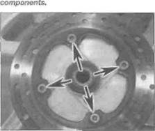
8.3 The minimum disc thickness is marked on each disc
Дата добавления: 2015-10-29; просмотров: 128 | Нарушение авторских прав
| <== предыдущая страница | | | следующая страница ==> |
| Tighten the mounting bolt to the specified torque | | | Remove the split pin (A) and withdraw the clevis pin (B) |