Читайте также:
|

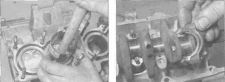
24.26b... then lower the connecting rod and piston into the bore...
connecting rod and cap and will be either a 1 or a 2 (see illustration). 22 A range of bearing shells is available. To select the correct bearing for a particular big-end, using the table below cross-refer the crankpin journal size letter (stamped on the web) with the connecting rod size number (stamped on the rod) to determine the colour code of the bearing required. For example, if the connecting rod size is 2, and the crankpin 3lze is A, then the bearing required is Green. The colour is marked on the side of the shell (see illustration).
Bearing shell colour code location (arrowed)
Connecting rod selection
23 If a connecting rod needs to be renewed,
the weight of the new rod needs to be
matched to the rod it is replacing. The
connecting rod weight code is marked on the
flat face of the connecting rod and cap and
will be either an A. B, or С (see illustration
24.21b).
Installation
24 On L, N and R models, and if required on J and К models (it can be done later), install the pistons onto the connecting rods (see Section 25).
25 Install the bearing shells in the connecting rods and caps, aligning the notch in the bearing with the groove in the rod or cap (see illustration 24.14).
26 On L, N and R models, lubricate the pistons, rings and cylinder bore with clean engine oil. Insert the piston/connecting rod assembly into the top of its bore, taking care not to allow the connecting rod to mark the bore. Make sure the IN mark on the piston crown is on the inlet side of the bore and the connecting rod is the right way round (see Step 3). then carefully compress and feed
24.26a Clamp the rings in position by tightening the bands on the compressor...
each piston ring into the bore until the piston crown is flush wltn the top of the bore. If available, a piston ring compressor makes installation a lot easier (see illustrations). Turn the crankcase upside down. Lubricate the shells with molybdenum disulphide oil (a 50/50 mixture of molybdenum disulphide grease and clean engine oil), then lower the crankshaft into position in the upper crankcase, making sure all bearings remain in place (see illustration 27.23 and 27.3).
27 Ensure that the connecting rod bearing Insert is still correctly installed. Liberally lubricate the crankpin with molybdenum disulphide oil (a 50/50 mixture of molybdenum disulphide grease and clean engine oil). Fit the connecting rod onto the crankpin, on L, N and R models taking care not to mark the cylinder bores.
28 Fit the bearing cap with its shell onto the connecting rod (see illustration). Make sure the cap is fitted the correct way around so the connecting rod and bearing cap weight/size markings are correctly aligned.
29 Lubricate the threads and seats of the cap nuts with clean engine oil. Ht the nuts to the connecting rod and tighten them evenly, in two or three stages, to the specified torque setting (see illustration).
30 Check that the crankshaft is free to rotate easily. Check to make sure that all components have been returned to their original locations using the marks made on disassembly.
|
| a | , | d | " wj |
| Щам | |||
| Br. |
Дата добавления: 2015-10-29; просмотров: 188 | Нарушение авторских прав
| <== предыдущая страница | | | следующая страница ==> |
| Cylinder bores | | | Renew the piston and pin |