Читайте также:
|
Since we are using ESP method it is will be more convenient to use a horizontal X-mas tree. The simulations showed that the most efficient method for pumping oil through flowlines was the ESP method and different analyses showed that intervention costs of the ESP system with non-failure operations has been reduced. Also we have to consider that our hypothetical field is a big oil field that means we expect more oil to be produced, which leads to a huge well intervention so it is will be more relevant to use an horizontal X-mas tree and we produce heavy-oil (presents low gas/oil ratio) which is more favorable to use ESPs. [5]
The physical designs on X-mas trees distinguish on: type of X-mas tree, development, and the oil field. The X-mas tree designed to direct and control formation fluids from the well, controls the well pressure during production in another words X-mas tree is kind of well control equipment. After the well completion, the X-mas tree is used in testing the oil and gas. Subsea wells and thus trees usually flow through flowlines to Floating Production and Offloading Vessel or FPSO. [7]
A simple X-mas tree is located above the wellhead and it consists of a single master valve at the lower end a flow tee at the upper end, which splits the flow in three directions. The horizontal outlets lead to a wing valves. A swab valve is located vertically above the master valve on the top of the tree. The swab valve allows the vertical access to the tubing trying the master valve to secure it test well. The master and wing valves are used to stop and start flow as desired. The X-mas tree provide electrical signal to umbilical, access to production / annulus bores and provide electrical signal to DHSV equipment. [7]
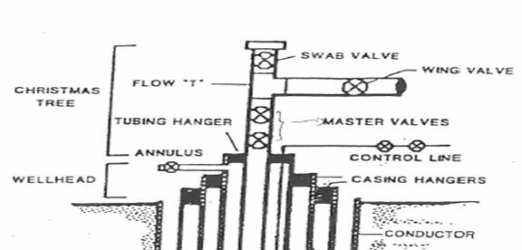
Figure 5: Design of X-mas tree
6. Carry out a top-down FMECA for the subsea production system (hint: system breakdown structure from but not including riser to but not including wellhead).
 |
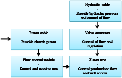
Figure 6: Functional block diagram
System: Subsea production system Performed by: Ivan Limanski
Ref. drawing: no Date: 14.09.2015
| Description of unit | Description of failure | Effect of failure | ||||||||
| Ref. No. | Function | Operational Mode | Failure Mode | Failure Cause or mechanism | Detection of failure | Local Effects | Global Effects | Failure Rate | Severity ranking | Risk reducing measures |
| Electric power supply. | Used for all modes and shell be available all the time | System is shutdown, no electrical signal | Corrosion / Erosion of electric and power cables, worn cables. | Equipment doesn’t respond. Visual detection. Gauges can show if there is no signal | A choke doesn’t respond. | There is a chance for oil spill, and for worst case scenario due no signal from control panel | 0.05 p/year | H | Condition based maintenance. Regular visual check. | |
| Control of Flow | Open | Failure in stopping production | Barriers and control device fails | Pressure and flow gauges showing reproduction of the flow | Failure of one of the barriers decreases reliability of the system | Chance for oil spill, environment problems, which lead to economical and money loss. | 0.01 p/year | M | Preventive maintenance | |
| Production is stopped. | Outflow in hydraulic system due failure of fail-safe equipment | Pressure and flow gauges showing, that flow has stopped. | Control on equipment, if it is necessary change / repair. | If production is stopped, money loss. | 0.05 p/year | H | Preventive maintenance | |||
| Closed | Failure in producing production | Outflow in hydraulic system due cause of mechanical failure of equipment | Pressure and flow gauges showing, that there is no production | Control on equipment, if it is necessary change / repair. | If production is stopped, money loss. | 0.05 p/year | M | Preventive maintenance | ||
| Production is backup while being closed | Valves and flow control module mechanical failures. | Pressure and flow gauges showing reproduction of the flow | Can lead to overload in Floating Production Storage. | Chance for oil spill, environment problems, which lead to economical and money loss. | 0.01 p/year | H | Preventive Maintenance |
Table 2: FMECA Form
Failure mode is the observed effect of a failure and the failure mechanism is the mechanism causing the failure.
7. Calculate system reliability for the subsea production system (hint: reliability block diagram) you have sketched in 3.
We have Series systems: systems where all the components must be working for the system to be successful. The reliability of such a model can be found by multiplying the reliability (pi) of each component:
System reliability = 
Parallell systems: systems where at least one component must be working for the system to work. The reliability of such a system can be found by combining the reliabilities (pi) of the components as:
System reliability = 
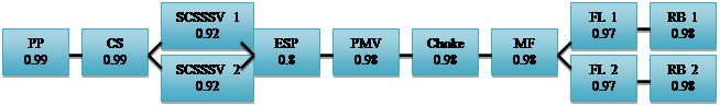
Figure 7: Reliability block diagram [9] [10]
PP: Production Packer
CS: Completion String
SCSSSV: Surface Controlled Sub Surface Safety Valve
ESP: Electrical Submersible Pump
PMV: Production Master Valve
MF: Manifold
FL: Flow Line module
RB: Riser Base
Probability for the component is:
h =  =
=
 = 0,66
Дата добавления: 2015-10-23; просмотров: 228 | Нарушение авторских прав
| <== предыдущая страница | | | следующая страница ==> |
| Describe the upper completion in detail from interface with lower completion to, and including, the tubing hanger. | | | Choose and describe control method for the field. |