|
Читайте также: |
LABORATORY WORK
Quantification of Microstructure and Texture
Sample Preparation Techniques for Optical Microscopy
Most images we will look at of metallic materials are the result of optical microscopy of prepared samples, and metallography is simply the name given to the systematic method used to examine the structure of materials.
Sectioning
The first step in the process of producing a specimen suitable for observation in the microscope is to obtain a suitably sized piece, which may need to be cut to the right size. When cutting a specimen from a larger piece of material, care must be taken to ensure that it is representative of the features found in the larger sample, or that it contains all the information required to investigate a feature of interest.
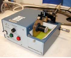
For this reason, even when the artefact is sufficiently small to permit metallographic preparation, it may still be advantageous to section it so that potentially unrepresentative surface regions are not examined. Many cutting methods can be used to remove part of an artefact for metallographic preparation, but in certain circumstances the selection may be restricted due to the effect this may have on the microstructure. Abrasive cutting, for example using equipment such as that in Figure 1, may introduce a lot of damage and deformation into a specimen, and the high speed can cause heating of the sample which could alter the microstructure. For these reasons, low speed cutting processes are often used, such as the diamond saw shown in Figure 2.

| 
|
| Figure 1 – An SiC blade abrasive saw | Figure 2 – A diamond blade low speed cutting saw |

Figure 3 – Electric Discharge Machining (EDM) equipment
Electrically conductive specimens may also be cut using Electric Discharge Machining (EDM), sometimes called spark cutting, Figure 3. In this method the sample is submerged in a dielectric fluid and an electrode (often in the form of a wire) is brought close to its surface. Electric discharge occurs between the wire and the sample and some of the sample material is removed as a result. The slow movement of the electrode and the progressive removal of material by further discharges results in cutting. Although in the region if the cut the material is heated, the depth of the material affected by this cutting method is very low, and it is particularly suitable for hard materials that would otherwise be difficult to cut.
Mounting
Once a piece of material of the correct size has been obtained it is normally necessary to mount it in another material to facilitate handling and polishing, and to protect the specimen from damage. There are two broad classes of mounting methods; hot and cold mounting.
Hot mounting
Mounting materials are often polymers, and so the possibility exists to embed a specimen by melting a polymer and squeezing it around it. To do this special machines exist that can apply the correct cycles of heat and pressure with good reproducibility and at relatively high speeds (a typical cycle time of 20-40 minutes is common). Because of this, hot mounting is the method used for the majority of specimens. An example of a hot mounting machine is shown in figure 4.
In practice, hot mounting normally occurs at a temperature of about 150°C, and may use either a thermosetting plastic, e.g. phenolic resin, or a thermosoftening plastic e.g. acrylic resin (phenolics tend to be low cost, and acrylics have good clarity). These resins can sometimes have special additions to make them electrically conductive, which is important to prevent charging if the specimen is to be imaged in the SEM, or if an elecropolishing step is required later.

Figure 4 – An example of a hot mounting press
Shape of Mounted Specimens
A mounted specimen should have a thickness of about half its diameter in order to prevent the creation of a bevel during grinding and polishing (a non-flat surface). The edges of the specimen may also be rounded off with coarse grinding paper. On the upper side this will make the specimen more comfortable to hold, and on the lower side it will help to reduce wear on grinding papers and polishing cloths. For some automatic polishing machines it is important to have the right diameter, which is often 30 mm. A schematic diagram of a specimen is shown in Figure 7.
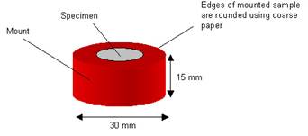
Figure 7 – A schematic diagram of a mounted specimen
Grinding
A grinding step is usually necessary to make the specimen flat (removing marks left from sectioning), and to remove the surface layers that would still show evidence of damage from sectioning in the microstructure. This is normally done using SiC paper under flowing water to wash away material removed, and can either be in the form of strips on static equipment or as discs on a rotating wheel (see Figure 8).

Figure 8 – A grinding setup with SiC paper strips and a grinding wheel with an SiC disc in use.
The normal procedure is to start with a coarse grade of SiC paper (large SiC particles) which removes material rapidly, but leaves large scratches, and then to progress to finer papers, each of which removes material less rapidly, but leaves a smoother surface. SiC papers are graded according to “grit” size, a number corresponding to the number of grains per square inch; smaller numbers mean coarser SiC particles. A typical starting paper would be 120 or 240 grit, followed by intermediate papers such as 320, 400, 600 or 800 grit. The final step is normally on 1200 grit paper, although 2500 and 4000 grit grades are available, and are used in some specialist polishing methods. Between each stage the specimen should be washed to prevent transport of coarse particles to a higher grade spoiling the grinding. An ultrasonic bath can also be used but is not necessary.
When grinding manually, moderate pressure is normally sufficient; heavy pressure is not required as it can cause further damage to the microstructure of the sample (rather than removing the damage induced by the sectioning process, as we are trying to do with this step), and also increases the risk of the specimen catching on the paper and being thrown off the wheel. The times required at each step can also be surprisingly short (often less than a minute). A useful way to tell is to rotate the specimen by 90° between papers. This way it is easy to see scratches that remain from the previous paper. When all of the scratches from the previous step have been removed, it is safe to proceed to the next paper.
Polishing
Once the surface to be observed has been revealed by grinding, it is polished to a reflective, scratch-free finish. This is performed on rotating wheels, with the option of automatic attachments, such as that shown in Figure 9. On such machines, the speed of wheel rotation and the pressure applied to the specimen can be varied and both will have an effect on the quality of the polish produced.

Figure 9 – An automatic polishing machine
The discs used in the machine are covered with soft cloth impregnated with abrasive diamond particles and a lubricant which can be water, alcohol or oil-based (each will give slightly different polishing behaviour and interaction with the specimen). There are two stages to polishing: a coarser polish of 30-3 µm at a relatively fast rotational speed (typically with diamond particles 6 microns in diameter which should remove the scratches produced from the finest grinding stage, and a speed of 300 rpm), and a finer polish <1µm at lower speed (typically with diamond particles 1 micron in diameter, and 100 rpm, to produce a smooth surface). A further step of polishing with 0.3-0.05 µm alumina slurry can also be used. Before using a finer polishing wheel the specimen should be washed thoroughly with warm soapy water followed by alcohol to prevent contamination of the disc. An ultrasonic bath may also be used.
To obtain even finer polishing, or for particularly difficult specimen, electropolishing may be used. In this method the specimen is made the anode in a suitable solution, and the conditions adjusted so that peaks on the surface dissolve faster than the troughs, thus tending to smooth the surface out. More information and details of specific electropolishing solutions and conditions can be found in the Smithells Metals Reference Book.
Poorly adapted polishing techniques can lead to the generation of artefacts in the samples. Two examples of such artefacts are shown in Figure 10.


Figure 10 – Artefacts caused by use of the incorrect polishing technique. The image on the left shows scratches which may persist in the sample as it has not been ground for enough time at each of the steps, or may indicate contamination of the polishing wheel with grit from a previous grade. The image on the right shows embedded polishing particles which result from the use of too high pressure during polishing.
Etching
Depending on the sample, an etching step after polishing may be necessary. The purpose of etching is to optically enhance microstructural features such as grain size and phases. Etching is essentially a controlled corrosion process, and selectively alters the surface based on composition, stress, or crystal structure, and this created contrast in the microscope due to differences in topography or reflectivity of the different phases or features. For example, in a pure material, an etchant (a reagent that chemically attacks the material being examined) will preferentially etch high energy sites such as grain boundaries. This results in a surface relief that enables different crystal orientations, grain boundaries, phases and precipitates to be easily distinguished, as shown diagrammatically in Figure 11.

Figure 11 – Schematic diagram of how a grain boundary is revealed in the microscope after etching.
Following the etching process there may be numerous small pits present on the surface. These etch pits are caused by localised chemical attack, and in most cases they do not represent features of the microstructure, although they may occur preferentially in regions of high local disorder, for example where there is a high concentration of dislocations. If the specimen is over etched, ie. etched for too long, these pits tend to grow, and obscure the main features to be observed. Should this occur, the specimen must be repolished (starting from around the 6µm diamond polish step) and the process repeated.
Etchants
The most common technique for etching is selective chemical etching and numerous formulations have been developed for different materials, and can be found in the literature. Common etchants often have three components:
• A corrosive agent (frequently acids)
• A modifier (such as an alcohol, glycerin, etc.)
• An oxidizer (such as hydrogen peroxide, Fe3+, etc.)
The table below gives some common etchants.
Дата добавления: 2015-10-26; просмотров: 152 | Нарушение авторских прав
| <== предыдущая страница | | | следующая страница ==> |
| Titration of acids of gastric contents. | | | Reflected Light Microscopy |