Читайте также:
|
• Internal micrometers are available for measuring bore diameters, but are expensive and unlikely to be available for home use. It is suggested that a set of telescoping gauges and small hole gauges, both of which must be used with an external micrometer, will suffice for taking internal measurements on a motorcycle.
| 46.000 | 0.490 | |
| = | sr | Г |
| IIIHIIIIIIIIIll I 40 45 | k | |
| I---- ' 4-U "— 40 0.500 | ||
3.6... and 0.004 mm on vernier scale
• Telescoping gauges can be used to measure internal diameters of components. Select a gauge with the correct size range, make sure its ends are clean and insert it into the bore. Expand the gauge, then lock Its position and withdraw it from the bore (see illustration 3.7). Measure across the gauge ends with a micrometer (see illustration 3.8).

3.7 Expand the telescoping gauge in the bore, lock its position...
| J | |
| ^a |
/;
3.8... then measure the gauge with a micrometer
3.10... then measure the gauge with a micrometer
• Very small diameter bores (such as valve
guides) are measured with a small hole gauge.
Once adjusted to a slip-fit inside the
component, its position is locked and the
gauge withdrawn for measurement with a
micrometer (see illustrations 3.9 and 3.10).
Vernier caliper
Note: The conventional linear and dial gauge type instruments are described. Digital types are easier to read, but are far more expensive.
• The vernier caliper does not provide the precision of a micrometer, but is versatile In being able to measure internal and external diameters. Some types also incorporate a depth gauge. It is ideal for measuring clutch plate friction material and spring free lengths.
• To use the conventional linear scale vernier, slacken off the vernier clamp screws (1) and set Its jaws over (2), or inside (3), the item to be measured (see illustration 3.11). Slide the jaw into contact, using the thumbwheel (4) for fine movement of the sliding scale (5) then tighten the clamp screws (1). Read off the main scale (6) where the zero on the sliding scale (5) intersects it, taking the whole number to the left of the zero; this provides the base measurement. View along the sliding scale and select the division which lines up exactly with any of the divisions on the main scale, noting that the divisions usually represents 0.C2 of a millimetre. Add this fine measurement to the base measurement to obtain the total reading.
Tools and Workshop Tips rep

|
1 Clamp screws
2 External jaws
3.11 Vernier component parts (linear gauge)
| Internal jaws Thumbwheel |
5 Sliding scale
Main scale
7 Depth gauge
Plastigauge
• Plastigauge is a plastic material which can be compressed between two surfaces to measure the oil clearance between them. The width of the compressed Plastigauge is measured against a calibrated scale to determine the clearance.
• Common uses of Plastigauge are for measuring the clearance between crankshaft journal and main bearing inserts, between crankshaft journal and big-end bearing inserts, and between camshaft and bearing surfaces. The following example describes big-end oil clearance measurement.
• Handle the Plastigauge material carefully to prevent distortion. Using a sharp knife, cut a length which corresponds with the width of the bearing being measured and place it carefully across the journal so that it is parallel with the shaft (see illustration 3.15). Carefully install both bearing shells and the connecting rod. Without rotating the rod on the journal tighten its bolts or nuts (as applicable) to the specified torque. The connecting rod and bearings are then disassembled and the crushed Plastigauge examined.
In the example shown the item measures 55.92 mm (see illustration 3.12):
Base measurement 55.00 mm
Fine measurement 00.92 mm
Total figure 55.92 mm
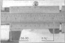
3.12 Vernier gauge reading of 55.92 mm

3.13 Vernier component parts (dial gauge)
| 5 Main scale 6 Sliding scale 7 Dial gauge |
1 Clamp screw
2 External jaws
3 Internal jaws
4 Thumbwheel
• Some vernier calipers are equipped with a dial gauge for fine measurement. Before use, check that the jaws are clean, then close them fully and check that the dial gauge reads zero. If necessary adjust the gauge ring accordingly. Slacken the vernier clamp screw (1) and set its jaws over (2), or Inside (3), the item to be measured (see illustration 3.13), Slide the jaws into contact, using the thumbwheel (4) for fine movement. Read off the main scale (5) where the edge of the sliding scale (6) intersects it, taking the whole number to the left of the zero; this provides the base measurement. Read off the needle position on the dial gauge (7) scale to provide the fine measurement; each division represents 0.05 of a millimetre. Add this fine measurement to the base measurement to obtain the total reading.
In the example shown the item measures 55.95 mm (see illustration 3.14):
Base measurement 55.00 mm
Fine measurement 00.95 mm
Total figure 55.95 mm
| .-——*. | J | 00.95 | ||
| шу i j\ | ||||
| NSK | Jm | |||
| 55.00 / 1 | ■ •** | .'« | *5 | |
3.14 Vernier gauge reading of 55.95 mm

3.15 Plastigauge placed across shaft journal

|
| 3.16 Measuring the width of the crushed Plastigauge |
• Using the scale provided in the Plastigauge kit. measure the width of the material to determine the oil clearance (see illustration 3.16). Always remove all traces of Plastigauge after use using your fingernails. Caution: Arriving at the correct clearance demands that the assembly is torqued correctly, according to the settings and sequence (where applicable) provided by the motorcycle manufacturer.
ref.12 Tools and Workshop Tips
Dial gauge or DTI (Dial Test Indicator)
• A dial gauge can be used to accurately measure small amounts of movement. Typical uses are measuring shaft runout or shaft endfloat (sideplay) and setting piston position for ignition timing on two-strokes. A dial gauge set usually comes with a range of different probes and adapters and mounting equipment.
• The gauge needle must point to zero when at rest. Rotate the ring around its periphery to zero the gauge.
• Check that the gauge is capable of reading the extent of movement in the work. Most gauges have a small dial set In the face which records whole millimetres of movement as well as the fine scale around the face periphery which is calibrated in 0.01 mm divisions. Read off the small dial first to obtain the base measurement, then add the measurement from the fine scale to obtain the total reading.
In the example shown the gauge reads 1.48 mm (see illustration 3.17):
Base measurement 1.00 mm
Fine measurement 0.48 mm
Total figure 1.48 mm
maximum gauge reading as the amount of runout in the shaft. Note: The reading obtained will be total runout at that point -some manufacturers specify that the runout figure is halved to compare with their specified runout limit.
• Endfloat (sideplay) measurement requires that the gauge is mounted securely to the surrounding component with its probe touching the end of the shaft. Using hand pressure, push and pull on the shaft noting the maximum endfloat recorded on the gauge (see illustration 3.19).

Дата добавления: 2015-10-29; просмотров: 184 | Нарушение авторских прав
| <== предыдущая страница | | | следующая страница ==> |
| And sealing compounds | | | Oil pressure gauge and take-off point adapter (arrow) |