Читайте также:
|
Standard bearings are used within reduction units as shaft supports. The bearing technical features are outlined in catalogues and reference books.
It’s generally recommended to fit shafts into bearings of non-regulated type to simplify assembly and improve unit reliability
In particular, the ball radial single row bearing belongs to that type of bearings. It’s designed to resist both radial and axle loads produced in both directions.
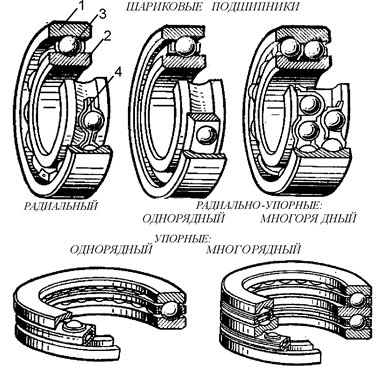
Rolling bearings (Fig.5) consist of outside (1) and inner (2) rings, with rolling elements (3)- balls, rolls fit between them.
To avoid interacting of rolling elements they are separated with separator (4)
 Fig 5. Main types of rolling bearings
| Benefits: high efficiency and low heating; high reliability and load resistance capability; low cost at mass production; high rate of changeability.. Disadvantages: short service life upon shock and vibration loads; large radial size; high noise during high speed ofrotation. |
Bearings of the same type having the same diameter d have different outside diameters D and width B that corresponds to dimensional series (Fig.6)

| Fig 6: Dimensional series of rolling bearings: 1 – super light; 2 – light; 3 – light and wide; 4 – medium; 5 – medium and wide; 6 – heavy |
Types of bearings:
ball rolling type – 0;
- ball radial one with short cylindrical rolls– 2;
- rolling radial with long rolls - 4;
- ball radial-supporting single row– 6;
- rolling conic – 7;
- ball supporting – 8.
Example of bearing symbol –
To be read from right to the left: first two digits (08) stand for bearing diameter (08 to be multiplied by 5, d=40mm); 3rd digit stands for the series (2 is a light series); 4th digit means type of the bearing (7 is rolling conic).
For the units under development the rolling bearings should not be designed, they are selected from the catalogue tables subject to the bearing type.
Selection of bearing type depends upon type of mechanical gearing, capacity to be transmitted, required service life of the unit (or individual assemblies) etc.
For cylindrical gearings the ball and rolling bearings are utilized.
 Fig. 7
| For this coursework it’s recommended to use (Fig.7) radial single row ball bearing (GOST 8338-75) as follows
for fast speed (input) shaft – ball bearings of medium series;
for low speed (output) shaft - ball bearings of light series
 – and outside diameters of the bearing; – and outside diameters of the bearing;  – width of rings. – width of rings.
|
Alongside the shaft diameter under the bearing inner ring for selected series all bearing parameters should be measured to perform further design work. It’s recommended to indicate the values defined as per the following table.
Major rolling bearing parameters under GOST 8338-75 standard
| Parameter | Symbol | Shaft 1 | Shaft 2 |
| Bearing symbol | |||
| Inner ring hole diameter,mm | 
| ||
| Outside surface of outside ring diameter,mm | 
| ||
| Bearing width,mm | 
| ||
| Bearing facet size, mm | 
| ||
| Rolling element diameter, mm | 
|
Radial single row ball bearing as per GOST 8338-
| Bearing symbol | d | D | В | r | Balls | Weight,kg | С, кН | С0, кН | |
| Dw | z | ||||||||
| Light series of diameters 2, narrow series of widths 0 | |||||||||
| 1,5 | 7,94 | 0,12 | 14,0 | 6,95 | |||||
| 1,5 | 9,53 | 0,20 | 19,5 | 10,0 | |||||
| 2,0 | 11,11 | 0,29 | 25,5 | 13,7 | |||||
| 2,0 | 12,7 | 0,36 | 32,0 | 17,8 | |||||
| 2,0 | 12,7 | 0,41 | 33,2 | 18,6 | |||||
| 2,0 | 12,7 | 0,47 | 35,1 | 19,8 | |||||
| 2,5 | 14,29 | 0,60 | 43,6 | 25,0 | |||||
| 2,5 | 15,88 | 0,80 | 52,0 | 31,0 | |||||
| 2,5 | 16,67 | 0,98 | 56,0 | 34,0 | |||||
| 2,5 | 17,46 | 1,08 | 61,8 | 37,5 | |||||
| 2,5 | 17,46 | 1,18 | 66,3 | 41,0 | |||||
| 3,0 | 19,05 | 1,40 | 70,2 | 45,0 | |||||
| 3,0 | 19,84 | 1,80 | 83,2 | 53,0 | |||||
| 3,0 | 22,23 | 2,2 | 95,6 | 62,0 | |||||
| 3,5 | 25,4 | 3,2 | 124,0 | 79,0 | |||||
| Medium series of diameters 2, narrow series of widths 0 | |||||||||
| 2,0 | 9,53 | 0,14 | 15,9 | 7,8 | |||||
| 2,0 | 11,51 | 0,23 | 22,5 | 11,4 | |||||
| 2,0 | 12,3 | 0,34 | 28,1 | 14,6 | |||||
| 2,5 | 14,29 | 0,44 | 33,2 | 18,0 | |||||
| 2,5 | 15,08 | 0,63 | 41,0 | 22,4 | |||||
| 2,5 | 17,46 | 0,83 | 52,7 | 30,0 | |||||
| 3,0 | 19,05 | 1,08 | 61,8 | 36,0 | |||||
| 3,0 | 20,64 | 1,35 | 71,5 | 41,5 | |||||
| 3,5 | 22,23 | 1,70 | 81,9 | 48,0 | |||||
| 3,5 | 23,81 | 2,11 | 92,3 | 56,0 | |||||
| 3,5 | 25,4 | 2,60 | 104,0 | 63,0 | |||||
| 3,5 | 26,99 | 3,10 | 112,0 | 72,5 | |||||
| 3,5 | 28,58 | 3,60 | 124,0 | 80,0 | |||||
| 4,0 | 30,16 | 4,30 | 133,0 | 90,0 | |||||
| 4,0 | 31,75 | 5,10 | 143,0 | 99,0 | |||||
| 4,0 | 36,51 | 7,00 | 174,0 | 132,0 |
Note: Example of symbol of r adial single row ball bearing of light series of diameters 2, series of widths 0and dimensions of d=50mm, D=110mm, B=22 mm: Bearing 212 GOST 8338-75
The bearings must be securely insulated from open air to avoid dust and dirt ingress and lubrication leakage. For this purpose the sleeves can be used (GOST 8752-79).
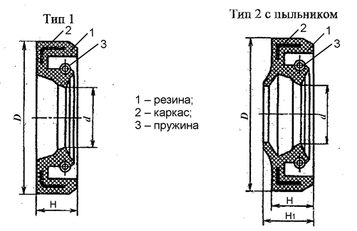
The sleeve is a compaction having a form of a ring made of reinforced oil resistant rubber with spring incorporated band (fig 7).
The frame provides the rigidity feature for the sleeve and ensures its secure fit into the housing element without any additional fixture. Band spring allows compacting part of the sleeve to securely hold the shaft surface.
The sleeve shall be fit into the bearing cap, it is pressed to the shaft by means if its own tension forces and tension force of the spring. The sleeve dimensions are to be selected as per shaft diameter.
Outside ring of the bearing is mounted in the shell by means of the cap, for instance as per GOST 18511-73* or per GOST 18512-73*. The screwed caps are convenient during service because they provide the access to individual bearing for inspection without reduction unit disassembling
GOST 18511-73* standard defines the design and dimensions for face end dumb caps.
GOST 18512-73* standard defines the design and dimensions for face end caps with hole for the sleeve compaction, designed to ensure sealing of rolling bearing elements, axial fixture and axial load resistance. As a compaction the reinforced rubber sleeves are utilized to secure the shafts according to GOST 8752-79 standard.

Fig. 7. Reinforced rubber sleeves
General dimensions of reinforced rubber sleeves (per GOST 8752-79)
| Diameter | Width of sleeve | Diameter | Width of sleeve | ||||

| 
| 
| 
| 
| 
| 
| 
|
| 30,32 | 55,56,58 | ||||||
| 30,35 | |||||||
| 63,65 | |||||||
| 18,19,20 | 70,71 | ||||||
| 20,21,22 | |||||||
| 23,24 | |||||||
| 90,92,95 | |||||||
| 30,32 | |||||||
| 52,58 | |||||||
| 60,62 | |||||||
| 48,50 | |||||||
Note: example of type 1 sleeve symbol for shaft with outside diameter of  mm:
mm:
Sleeve 1-50´70 per GOST 8752-79
Dimensions of face end dumb caps (GOST 18511-73) 
Note: example of type 2 dumb cap of design 1 symbol with diameter of  mm:
mm:
21-62 GOST 18511-73* cap
Dimensions of face end caps with hole for sleeve compaction (GOST 18512-73)

Note: 1. For dimension for sleeve compaction refer to GOST 8752-79.
2. Hole diameter in the cap to be defined as per corresponding shaft or couple diameter
3. Example of type 1 cap of design 2 symbol with diameter of  mm:
mm:
12-68X35 GOST 18512-73* cap
Дата добавления: 2015-10-31; просмотров: 101 | Нарушение авторских прав
| <== предыдущая страница | | | следующая страница ==> |
| Design-basis calculation of the shafts | | | Test calculation of output shaft fatigue strength |