|
Читайте также: |
- When the user operates the DVR system, video surveillance mode will be shown first after booting.
- Real-time live images are displayed. (Max 16ch)
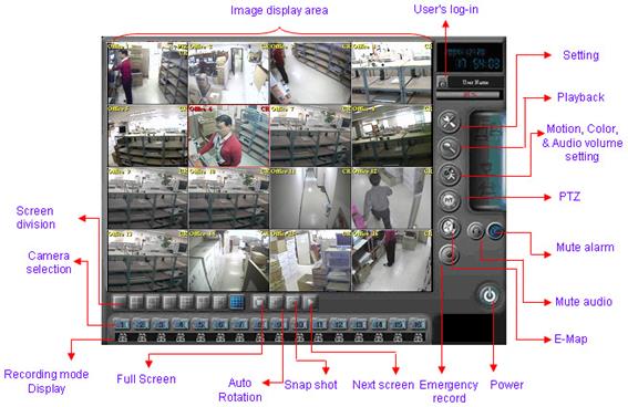
1.1 Main screen
1.1.1. Video display area – Real-time live images are displayed maximum 16 channels.
The total display speed is different according to the model no.
1.1.2. Camera selection button (1~16)

- The user can select each camera by choosing the button.
- Double-click of each channel on the screen will bring the same effect.
1.1.3. Screen division selection button
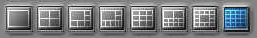
- The user can select screen division mode by choosing the button.
- 1,4,6,8,9,10,13,16 channel screen divisions are available.
1.1.4. Full screen mode
 - Real-time live image display part is extended to whole screen by pressing this
button.
- If the user clicks the right button of the mouse, the screen will go back to the
pre-mode.
1.1. 5. Automatic Rotation
 - Displayed screen is automatically rotated according to the screen rotation period
as set in “Setting” part.
- This function works with the current screen division mode.
For example, if the user operates this function while 4 channel screen division
mode, the screen will be automatically rotated in the divided screen as 4 parts.
1.1. 6. Snap shot
 - This button operates snap shot function which captures the currently displayed
live image to print picture or save as a file.
For example, if the user presses this button in 16 channel mode, the 16 channel
mode image will be captured and displayed in the snap shot mode.
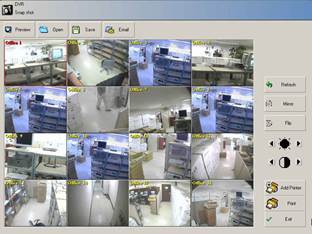
- Preview: Print preview
- Save: The user can save the captured image in FDD or HDD folder, network, and
USB saving facility.
- E-mail: The user can e-mail the captured image to the e-mail address set in the
Environment set up / Network or another address by pressing E-mail button.
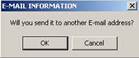 |
If the user clicks the cancel button of the below box, the
image will be sent to the address set in the Environment set
up / Network.
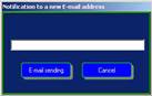 |
If If the user clicks the OK button, the address input box will
be shown as the left image.
In this case, the image will be sent to the address that the
user inputted in the box.
- Color control: The user can control the brightness & contrast of captured image here.
- Mirror & Flip: The user can reverse the captured image as upside down & left side
right.
- Add printer: The user can add new printer by pressing this button.
- Print: The user can print the captured image through the designated printer.
1.1.7. Next channel button
 - The screen moves to the next channel in 1 channel mode and in 4 channel
mode or more, the screen will go to the next 4 channel or more mode.
For example, if the user clicks this button while watching 1~4 channels in
4 channel mode, the screen will go to 4~8 channel.
1.1. 8. User’s log-in button
 - This button operates the user’s log-in to enter the DVR user’s
mode. If the user does not log-in, the user can use only the
 limited functions.
- User can be registered in the “User” part of Environment
setup. Please see the details in Environment setup part of this
manual.
1.1.9. Setting button
 |
- This button opens the Environment Setup screen.
1.1.10. Play back button
 |
- This button opens the search screen to play back the recorded image.
1.1.11. Motion & Color button
 |
- This button opens the screen for motion detection area & color setting as per
channel, and audio volume control.
1.1.12. PTZ control button
 |
- This button opens PTZ control box.
1.1.13. E-MAP (Electronic map) button
 |
- This button opens E-map screen.
1.1.14. Emergency record button

- This button operates recording immediately in an emergency.
1.1.15. Mute audio button
 |
- This button stops audio playback.
- If the user puts this button once more, the audio data will be played again.
1.1.16. Mute alarm button
 |
- This button stops the automatic event alarm sound.
- If the user presses this button once more, the alarm sound will be played again.
1.1.17. Power off button
 |
- This button turns off the system.
1.1.18. Recording mode information display
 |
Sensor Recording Motion detection Recording Continuous & Emergency Recording
- Recording mode information is displayed as the setting in “Environment Setup”.
- Clicking the recording status button, it starts the emergency recording.
Emergency Recording status is  .
.
1.1.19. Date & Time display
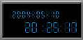 - Current system date & time are displayed here.
- The user can change current system time here by double-click.
- If the user changed the system time after the system HDD had
Been overwritten more than one time, the residual quantity
is indicated as 99%.
1.1.20. HDD consumption rate indication
 |
- Currently used HDD capacity is displayed.
- When all VDB is full and the overwriting starts, it restarts from 0%.
- If the user changed the system time after the HDD had been overwritten more than one
time, the used HDD capacity is indicated as 99%.
1.1.21. Network connection status & Two-way audio communication connection display

- This part shows the remote client connection status.
- The lamp is on when 1 or more remote client is connected.
 - If two-way audio communication is requested while the remote client
is connected, the status indicated as the left picture and two-way
audio communication is available if microphone & speaker are connected.
- The currently connected user name & IP are shown by click on the icon.
1.1.22. Sensor & Relay status display
 |
- The lamp is on when the sensor & relay is in operation.
- The sensor & Relay image is flickering when sensor & relay event happens.
- If the user double-clicks the displayed part, the below box will be open.
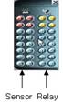 |
- Sensor & relay number that currently in operation will be shown.
- Red number shows sensor status and yellow number shows relay status.
- Connectable sensor or relay number is different according to the model no.
 2
2
Chapter
Дата добавления: 2015-08-27; просмотров: 61 | Нарушение авторских прав
| <== предыдущая страница | | | следующая страница ==> |
| User Setting | | | User log-in |