|
Читайте также: |
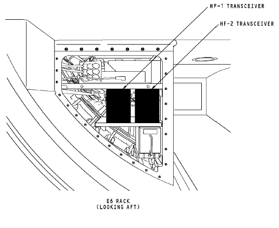
The radio communication panels are on the P8 aft electronics panel. The audio control panels (ACPs) are part of the flight interphone system. The ACPs have an interface with the HF communication system through the REU. The captain and first officer ACPs are on the P8 aft electronics panel. The first observer ACP is on the P5 aft overhead panel.


The HF transceivers are on the E6-2 shelf.
ANTENNA COMPONENT LOCATIONS
General
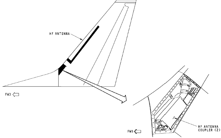
The antenna couplers are inside the vertical stabilizer.
WARNING: MAKE SURE PERSONNEL STAY A MINIMUM OF SIX FEET (TWO METERS) AWAY FROM THE VERTICAL STABILIZER WHEN THE HF SYSTEM TRANSMITS.
RF ENERGY FROM THE HF COMMUNICATION ANTENNA CAN CAUSE INJURIES TO PERSONNEL.
HF COMMUNICATION SYSTEM – INTERFACES
Power
The 115v ac transfer (XFR) bus supplies three-phase power to the HF transceiver.
The transceiver supplies 115v ac and 28v dc power to the HF
antenna coupler.
HF Transceiver
The HF transceiver has an interface with these components:
· RCP 1, 2, and 3
· Selective calling (SELCAL) decoder
· Remote electronics unit (REU)
· HF antenna coupler
· Flight data acquisition unit
· Proximity switch electronics unit (PSEU).
Radio Communication Panel
RCP 1 supplies frequency information to the HF 1 transceiver on an ARINC 429 bus to port A and to the HF 2 transceiver on port B. RCP 2 supplies frequency information to the HF 1 transceiver on an ARINC 429 bus to port B and to the HF 2 transceiver on port A. For more information about tuning interfaces, see HF Communication System - Tuning Interfaces.
The HF transceiver supplies the condition of the transceiver to the radio communication panels. The condition of the transceiver is one of the two: OK or FAILED.
The radio communication panel supplies these to the HF transceiver:
· Amplitude modulated or single side-band control
· Tuning data
· Port select discrete.

RADIO COMMUNICATION PANEL
Antenna Couplers
The antenna couplers supply these to the transceivers:
· Key interlock
· Tune in progress
· Received RF
· RF fault
· Coupler fault.
The antenna coupler opens the key interlock discrete to stop the transceiver transmit mode. The coupler sends the tune in progress discrete to request tuning power from the transceiver. The RF fault is sent to the transceiver when the coupler detects a fault external to the coupler. The coupler sends the coupler fault discrete to the transceiver when it detects an internal failure.
Received RF from the antenna is sent to the transceiver during receive mode.
The antenna couplers share one common HF antenna. During the transmit mode,
only one coupler has an electrical interface with the antenna. The on-side coupler sends the off-side coupler an inhibit discrete to prevent the off-side radio from transmitting. The couplers supply transmitted RF to theantenna.
They receive push-to-talk (PTT) from the REU to enable the the coupler tune mode.
The HF transceiver supplies these to the antenna coupler:
· Transmitted RF
· RF carrier during tune mode
· Rechannel pulse.
Modulated RF is sent to the antenna through the antenna coupler to be ransmitted. During tune mode, a low wattage RF carrier signal is sent to the coupler to match impedance between the transceiver and the antenna. The transceiver
sends the rechannel pulse to start the coupler home sequence mode.
HF Antenna
The HF antenna receives an RF signal from the antenna coupler and transmits the RF signal to other airplane and ground HF communication systems. The antenna also receives incoming RF signals and sends the RF signals to the antenna coupler.
Дата добавления: 2015-10-23; просмотров: 135 | Нарушение авторских прав
| <== предыдущая страница | | | следующая страница ==> |
| System Components | | | Training Information Point |