|
Читайте также: |
Acircular beam 17.5° wide is just sufficient to cover the whole disc of the Earth visible from a geostationary satellite. Such a beam has a beam edge gain of about 16dBi and it is generally provided by a horn antenna.
For most purposes, coverage of the whole visible Earth is not necessary, in which case it is also not desirable. Antennas with higher gain which, nevertheless, cover the required service area can provide much greater transmission capacity for given transponder power than global coverage antennas. Furthermore, frequency coordination of such satellites with others operating in the same frequency band is made easier, and the possibility may arise for frequency re-use within the satellite network if beams do not overlap.
The basic high gain antenna is an offset fed reflector, generating an approximately circular beam. The beam edge gain of such an antenna is given approximately by Equation 51.1 where D is the half power beamwidth in degrees.

However, it is so important to obtain the highest feasible gain from a satellite antenna that it is usual to adopt a more complex antenna design, producing a pattern of illumination on the Earth's surface (called the 'footprint') which matches closely the geographical area which is to be served. Thus, for example, INTELSAT V has six antennas for access to and from the transponders and two of them, optimised to generate beams from a mid-Atlantic orbital location which serve areas on both sides of the Atlantic Ocean where large amounts of traffic originate, take the form of front fed reflectors with an array of 88 carefully phased feed horns at their offset foci. (See Figure 51.10.) The corresponding feed horn arrays on INTELSAT VI antennas have 146 elements.
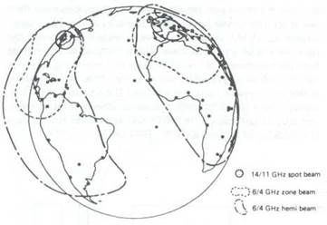
Figure 51.10 Approximate aerial beam coverage of INTELSAT V spacecraft for the Atlantic Ocean region
Дата добавления: 2015-07-20; просмотров: 121 | Нарушение авторских прав
| <== предыдущая страница | | | следующая страница ==> |
| The transponders | | | Modulation techniques |