The first INTELSAT IV satellite was launched in January 1971 but the design plan of the transponders for these satellites was highly innovative (Jilg, 1972) and it has remained a basic model for most satellites that have followed. The satellite used the 6GHz band for up-links and the 4GHz band for down-links. Figure 51.9 shows the basic elements.
Signals in the band 5.932GHz to 6.418GHz from the receive antenna were first amplified in a 6GHz tunnel diode amplifier (TDA) and then frequency translated by 2225MHz for further broadband amplification in a 4GHz TDA and a low level travelling wave tube (TWT). This part of the system had fourfold redundancy to achieve high reliability and long life. The signals were then split by a filter dividing network into 12 channels, each 36MHz wide and 40MHz spacing between centre frequencies. Each channel had its own redundant high level TWT amplifier rated at 6 watts single carrier saturated output power. The gain of the amplifiers for channels 1 to 8 was controllable in eight 3.6dB steps; for channels 9 to 12 there were four steps. The outputs of all of these amplifiers, after bandpass filtration to remove out of band distortion products, could be connected to one of two hom antennas covering the whole visible disc of the Earth. Alternatively, any or all of channels 1, 3, 5 and 7 could be connected by telecommand to spot beam antenna number 1 (half power beamwidth 4.5°) and similarly channels 2, 4, 6 and 8 had optional access to spot beam antenna number 2.
The principal characteristics of the transponder and antenna subsystems were as follows:
1. Receive system gain to noise temperature ratio (G/T) equal to -17.6dB/K.
2. Up-link power flux density at receive antenna for output TWT saturation equal to -73.7dBW/m2 to -55.7dBW/m2.
3. Transmit e.i.r.p. at single-carrier saturation: global beam equal to 22dBW per channel; spot beam equal to 33.7dBW channel.
4. The receive antennas were LH circularly polarised and the transmit antennas were RH circularly polarised.
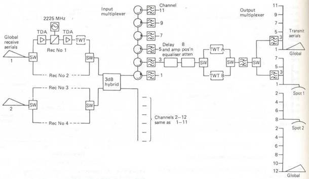
Figure 51.9 INTELSAT IV transponder
By way of contrast, the EUTELSATII design is very new, the first being launched in 1991. The 14GHz band is used for up-links and the UGHz and 12GHz band for down-links. The system employs 'frequency re-use' by dual linear polarisation, providing up to lGHz of usable bandwidth, some accessed by narrow band (36MHz) transponders and some by wide band (72MHz) transponders. All transponders have redundant TWT amplifiers rated at 50 watts single carrier saturated output.
Where the demand for satellite services is high it is economically advantageous to maximise the bandwidth that is available for signals. Many satellites, like EUTELSAT II, obtain two fold frequency re-use by dual polarisation. Many satellites are equipped to operate in more than one pair of frequency bands, typically having some transponders operating at 6GHz and 4GHz and others operating at 14GHz and ll/12GHz. In satellites serving extensive geographical areas, the transponder capacity may be enhanced by frequency re-use between non-overlapping spot beams. Thus, applying all of these frequency use techniques, the INTELSAT VI satellites have 38 transponders which use the 6 and 4 GHz bands 8 times over, plus 10 transponders which use the 14 and 11/12 GHz bands twice over.
At the sub-unit level, major changes are taking place. Solid state amplifiers have largely replaced TWTs in power amplifiers at 4GHz. There is a trend away from transponder power to bandwidth ratios appropriate to high performance earth stations and towards more powerful transponders suitable for small antenna earth station-s. Most radically, transponders and on board signal path switching systems are becoming optimised for digital transmission systems. On multi-beam satellites, in addition to long term flexibility switches which enable signal paths to be set up on a semi-permanent basis between a specified up-link beam and a specified down-link beam within a given frequency band, switch matrixes capable of reconfiguring beam to beam connections from millisecond to millisecond are now being taken into use for on-board switched time division multiple access systems (Watt, 1986). Development work is also in progress on on-board signal processing equipment which can demodulate up-linked digital signals, regenerate the digital waveform and assemble the signals in appropriate time division multiplex streams for more economical transmission back to Earth (Evans, 1986).
Exercise 1: Terms to know
| Transmission delay | -задержка передачи |
| Doppler Shift | -доплеровский сдвиг частоты |
| The free space transmission | -передача в свободном пространстве |
| Margin | -запас |
| Polarization discrimination | -поляризационная селекция |
| The transponder | -ретранслятор |
| Down-links | -линия связи ЛА - земля |
| Tunnel diode amplifier | -усилитель на туннельном диоде |
| TWT(travelling-ware tube) | -лампа бегущей волны (ЛБВ) |
| TWT amplifier | -усилитель на ЛБВ |
| Redundant high level TWT | -избыточный усилитель на ЛБВ высокого уровня |
| Carrier power | -мощность несущей |
| Bandpass filtration | -полоса пропускания |
| Horn antenna | -рупорная антенна |
| Output power | -выходная мощность |
| Saturation power | -мощность насыщения |
| To spot | -определять положение; определять координаты; располагать; делать разметку; опознавать |
| To split | -разделить |
| Redundancy | -избыточность; резервирование; дублирование; статическая неопределенность (системы) |
| Translate | -преобразовывать; трансформировать; пересчитывать (из одних единиц в другие); транспонировать (частоту) |
| Dual linear polarization | -двойная линейная поляризация |
| Spot beam | -сфокусированный луч; сфокусированный пучок |
| Overlap | -наложение; перекрытие; совмещение |
| Multi-beam satellites | -спутник связи с многолучевой антенной |
| Board signal path switching | -панель коммутации сигнальных каналов |
| Semi-permanent basis | -полупостоянный базис |
| On-board switched time division multiple access systems | -переключатель системы с временным разделением каналов |
| Linear | -линейная (аналоговая) |
Exercise 2: Answer the following questions:
1. Is the communication path always duplex in practical satellite systems? Why?
2. What are the main advantages and disadvantages of the GSO (the geostationary satellite orbit)?
3. What do you know about space-earth propagation? Give a short summary in Russian(51.4.2)
4. When was the 1-st INTELSAT- IV satellite launched?
5. What were the principal characteristics of the transponders and antenna subsystems for INTELSAT satellites?
6. What bands did the first INTELSAT satellite use for up-links and for down-links?
7. When was the 1-st EUTELSAT satellite launched?
8. Did it use the same bands (as INTELSAT) for up-links and for down-links?
9. Does the system employ “frequency re-use” by dual linear polarization?
10. In what cases is it economically advantageous to maximize the bandwidth that is available fir signals?
11. Is the development work in progress as far as transponders are concerned?
Дата добавления: 2015-07-20; просмотров: 113 | Нарушение авторских прав
| <== предыдущая страница | | | следующая страница ==> |
| Space-earth Propagation | | | Satellite antennas and footprints |