|
Читайте также: |
Figure 51.5 represents the communication chain in satellite communication in its simplest form. At one earth station, signals from a source modulate a carrier (M), the carrier is up-converted (U/C) to a radio frequency suitably for the up-link, amplified in a transmitter (Te) and radiated to the satellite receiving antenna. At the satellite, the received carrier is amplified (Rs), changed to the down-link frequency (F/C), amplified in a transmitter (Ts) and radiated to another earth station; this assembly of equipment in the satellite is called a transponder. At that second earth station the down-link carrier is received and amplified (Re), down-converted (D/C) and demodulated (D) so that the signal can be passed to its destination. In practical systems the communication path is often duplex, the return signal channel usually being transmitted through the same satellite transponder. A carrier transmitted from one earth station may be received at many earth stations. There may be several or many other pairs of earth stations passing carriers through the same satellite transponder simultaneously or in sequence, which is called multiple access. There may be other transponders in the satellite, isolated from one another by frequency separation, satellite antenna directivity or polarisation discrimination and relaying different groups of carriers. The techniques which allow satellite communication to be used in these various ways are reviewed later in this chapter.
The optimum choice of orbit for a satellite depends primarily on the mission. The geostationary satellite orbit (GSO) has several important advantages over other orbits that might be used for communication systems. A geostationary satellite, being stationary in the sky as seen from the Earth, is constantly in sight of a fixed earth station. The variation with time of the transmission delay is zero for an ideal geostationary satellite and it is small where good standards of satellite station keeping are maintained. Satellites in other orbits, such as those illustrated in Figure 51.6, move across the sky, so earth station antennas, if they are directional, must track the satellite movement.

Figure 51.5 The basic satellite communication chain

Figure 51.6 Some typical communication satellite orbits (not strictly to scale)
Most non-geostationary satellites periodically disappear below the horizon; if unbroken operation is required, several or many satellites must be deployed in suitable configured orbits and the communication links between earth stations must be transferred from one satellite to another at intervals ranging from several times per day down to several times per hour. Furthermore the motion of these satellites, relative to the earth stations, causes the earth station to earth station transmission time to vary with time, leading to synchronisation problems with high speed digital systems and doppler shift of signal frequencies in analogue systems.
However, the GSO has two serious disadvantages, which it shares with some elliptical orbits. The free space transmission loss between a satellite and an earth station and the transmission delay, earth station to earth station, are both very large. Figure 51.7 shows how these quantities vary with the altitude of the satellite above the Earth's surface (the transmission loss also varies with carrier frequency and the figure shows values for l0GHz).
Lower transmission loss for low altitude offers big advantages for some applications.
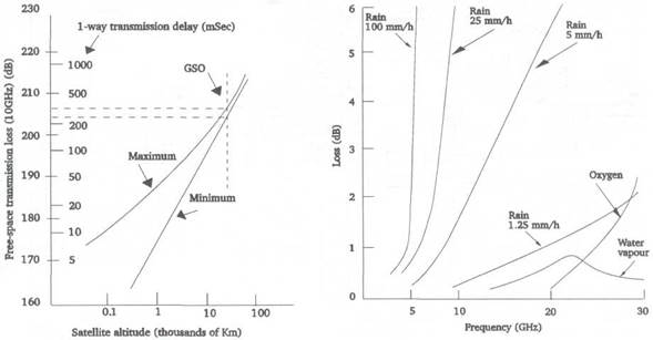
Figure 51.7 Transmission loss and delay as a function of satellite altitude Figure 51.8 An approximate indication of tropospheric absorption on space-
earth paths
Дата добавления: 2015-07-20; просмотров: 128 | Нарушение авторских прав
| <== предыдущая страница | | | следующая страница ==> |
| Telemetry, tracking and command | | | Space-earth Propagation |