Читайте также:
|
Why Current Transformers are Used. -A current transformer is an instrument transformer for the transformation of current from one value to another,usually a lower one, or for the transformation of current at a high voltage into a proportionate current at a low voltage with respect to earth potential. Current transformers are used in conjunction with alternating-current meters or instruments where the current to be measured is of such magnitude that the meter or instrument current coil cannot conveniently be made of sufficient carrying capacity. They are also used wherever high-voltage current has to be metered,because of the difficulty of providing adequate insulation in the meter itself. In this connection supply voltages exceeding 660 volts are considered to be high voltage. In meter practice current transformers are used wherever the current to be metered exceeds 100 amperes, and in some instances a lower value then this is regarded as the desirable maximum for direct measurement.
Construction of Current transformers. -A current transformer comprises a magnetic circuit, usually in the form of iron stampings assembled together to form a core, on which are wound two electric circuits called the primary winding and secondary winding respectively. The primary winding carries the current to be measured and is connected in the main circuit. The secondary winding carries a current proportional to the current to be measured and the secondary terminals are connected to the current winding of the meter or instrument: Both windings are insulated from the core and from each other. The secondary insulation is arranged to withstand a test pressure of 2,000 volts applied between the winding and the core for one minute. The insulation of the primary and secondary windings approximately equal to four times the voltage existing under working conditions. During this test the core and the secondary winding are connected together.
The primary circuit of a current transformer may consist of a single conductor in the form of a bar or cable instead of s winding, when the current to be measured is of the order of 600 amperes or more. In low-voltage circuits the current to be measured may be so heavy that it is not convenient to provide a primary integral with the transformer * and the latter then consists of an iron core of appropriate shape with secondary winding thereon, the whole being mounted on the busbar or cable. The nominal full-load current of a transformer is termed the “rated primary current” and is the value in amperes of the primary current marked on the rating plate. 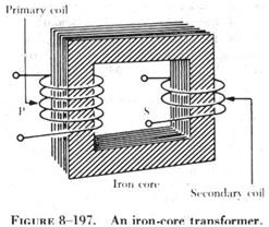
The secondary winding of a current transformer is usually constructed to deliver five amperes to the meter or instrument when rated primary current flows in the main circuit. This is referred to as the “rated secondary current” and five amperes is the standard value adopted in the most countries. In power-station practice it is not unusual for the meter to be separated from its current transformers by a distance of several hundred feet. The LR loss in the connecting leads together with the loss in the meter current coils may impose a burden in excess of the transformer rating if a five-ampere secondary current the loss in the leads can be substantially reduced and one ampere or 0.5 ampere values are permissible alternatives. Since the loss varies as the square of the current the adoption of one of these alternatives will reduce the loss in the leads to one-twenty-fifths or one-hundredth of the original value respectively.
The magnetic and electric circuits of a current transformer are represented diagrammatically in Fig. 14; the primary winding is shown surrounding one limb of the core and the secondary winding surrounding another. In actual practice the two windings would not be separated in this manner as the primary would be superimposed on the secondary, but they are shown thus for the sake of** clarity in the diagram. The primary terminals by the same letters enclosed in a circle. The cores of current transformers are usually built up with laminations of silicon-steel but where a high degree of accuracy is desired a high-permeability nickel-steel such as Mumetal or Permalloy may be used. Three types of magnetic circuit are in common use, namely, “ring-type”, “core-type”, and “shell-type” and are illustrated in Fig.8.
Дата добавления: 2015-08-20; просмотров: 50 | Нарушение авторских прав
| <== предыдущая страница | | | следующая страница ==> |
| Text 12. The Telephones | | | Text 15. Powerhouse auxiliary motors |