Читайте также:
|
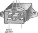
33.1a Regulator/rectifier - J and К models
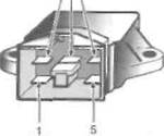
33.1b Regulator/rectifier-L, N and R models
Electrical system 9*25

|
| YELLOW |
| GREEN |
2 Connect the meter positive (+ve) probe to the red/white terminal and the negative (-ve] probe to the green terminal on the wiring connector and check for voltage with the ignition switched ON. Full battery voltage should be present. Switch the ignition switch OFF.
3 Switch the multimeter to the resistance (ohms) scale. Check for continuity between the green terminal of the wiring connector and earth on the frame. There should be continuity.
4 Check the resistance between any two yellow terminals of the wiring connector. A resistance reading of 0.1 to 0.5 ohms should be obtained between any two Yellow terminals of the wiring connector.
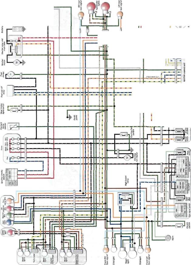
5 If the above checks do not provide the expected results check the wiring between the battery, regulator/rectifier and alternator (see the wiring diagrams at the end of this book).
6 If the wiring checks out, the regulator/rectifier unit is probably faulty. To check the unit, remove it from the bike (see below) and use a multimeter set to the appropriate resistance scale:o check the resistance between the various terminals on the regulator/rectifier (see illustrations). If the readings do not compare closely with those shown in the accompanying table the regulator/rectifier unit can be considered faulty. Note: The use of certain multimeters could lead to false readings being obtained, as could a low battery in the mete' and contact between the meter probes and your fingers. If the above check shows the regulator/rectifier unit to be faulty, take the unit to a dealer for confirmation of its condition before renewing it.
Replacement
7 Remove the seat cowling (see Chapter 8).
8 The regulator/rectifier is mojnted on the left-hand side of the rear sub-frame on J and К models, and on the right on L, N and R models (see illustration 33.1a or b).
9 Unscrew the two bolts securing the regulator/rectifier and remove i;, on J and К models noting the lead secured by the bottom bolt.
10 Connect the wiring connector. Install the new unit and tighten its bolts securely, not forgetting the lead with the bottom bolt on J and К models.
11 Install the seat cowling (see Chapter 8).
| Shindenqen unit - SS*57C | UNIT: Kfi | |||||
| _ ^ч*-чч + | R/W | V | Y | Y | G | |
| R/W | oo | CO | oo | oo | ||
| Y | 0.5-10 | 30 - 500 | 30- | 10-200 | ||
| Y | 0.5-10 | 30-500 | 30- | 10-200 | ||
| 30 - 500 | 30 - 500 | 10-200 | ||||
| Y | 0.5-10 | |||||
| G | 1-20 | 0.5-10 | 0.5-10 | 0.5 | -10 | "^\ |
| Sankendenki unit - V-><r >ЪЖ | UNIT: Kil | |||||
| >*^ | R/W | Y | Y | Y | G | |
| R/W | \^ | oo | oo | oo | oo | |
| Y | 0.5-10 | ^\ | oo | oo | oo | |
| Y | 0.5-10 | oo | ОС | oo | ||
| Y | 0.5-10 | 30 - 500 | 30 - 500 | 10-200 | ||
| G | 0.5-10 | 0.5- | -10 | ^\ | ||
| 1-20 | 0.5-Ю |
33.6a Test connections and date - J and К models
7?ie table applicable depends on the manufacturer of the regulator/rectifier oo = infinite resistance (no continuity)
UNIT:Kfi
| + | ||||||
| CO | CO | |||||
| 0.5-10 | oo | CO | CD | |||
| 0.5-10 | OO | CO | CO | |||
| 0.5-10 | oo | CO | oo | |||
| 0.7-15 | 0.5-10 | 0.5-10 | 0.5-10 | \ |
33.6b Test connections and data - L, N and R models
oo = infinite resistance (no continuity)
9*26 Electrical system
|

|
|
| Я |
| £ |
| =!l |
| гВДИЙ |
| ------ Eg * |
i
о
E
I
cc
i
и О
|
| Iqniln/n (nuilnf switch |
| Coolant Tlirotltu Fuatcut-olt F"ol Roar brake s '•""/» position relay *>umP "OMsmlch I |
| Clutch Xnpnibnuxwttet, им Wmteh switch ^- |
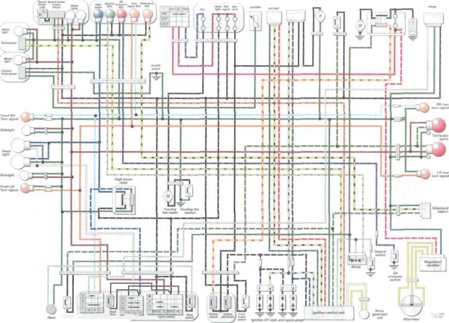
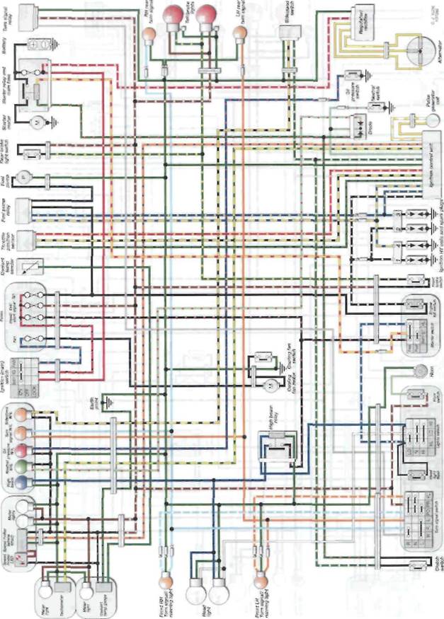
CBR400RR - L and N models
(0
9»28 Electrical system
|
о; if О
ее
с
о о
— ее ш о
Contents _____________
Дата добавления: 2015-10-29; просмотров: 162 | Нарушение авторских прав
| <== предыдущая страница | | | следующая страница ==> |
| Fit the clutch pushrod if removed | | | REPAIRS AND OVERHAUL |