Читайте также:
|
Unscrew and remove the two bolts (arrowed)...
A... then remove the front cover.
|
B... the shims...
29 Starter motor - disassembly, 5^ inspection and reassembly ^
Disassembly
1 Remove the starter motor (see Section 28).
2 Note the alignment marks between the main housing and the front and rear covers, or make your own if they aren't clear (see illustration).
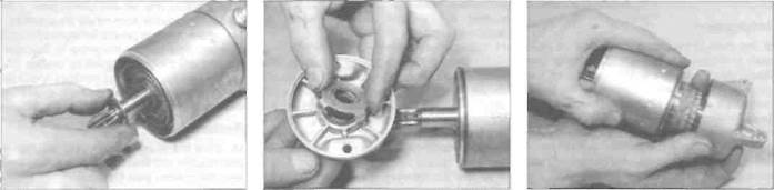
3 Unscrew the two long bolts, noting how the washers locate, and withdraw them from the starter motor (see illustration). Discard their O-rings as new ones must be used.
29.4c... and the tabbed washer
4 Wrap some insulating tape around the teeth on the end of the starter motor shaft - this will protect the oil seal from damage as the front cover is removed. Remove the front cover from the motor (see illustration). Remove the cover O-ring from the main housing and discard it as a new one must be used, Remove the shims from the front end of the armature shaft or the inside of the front cover. noting their correct fitted locations (see illustration). Also remove the tabbed thrust washer from the front cover (see illustration).
5 Remove the rear cover and brushplate assembly from the motor (see illustration),
29.5 Remove the rear cover
Remove the cover O-ring from the main housing and discard it as a new one must be used. Remove the shims from the rear end of the armature shaft or from inside the rear cover after the brushplate assembly has been removed.
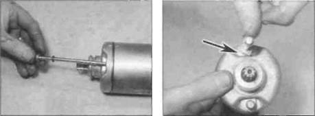
6 Withdraw the armature from the main housing.
7 Noting the correct fitted location of each component, unscrew the terminal nut and remove it along with its washer, the insulating washers and U-ring (see illustration). Withdraw the terminal bolt and brushplate assembly from the rear cover.
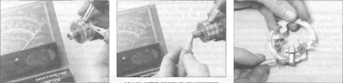
8 Lift the brush springs and slide the brushes out from their holders (see illustration).

|
Unscrew the nut (A) and remove the washers, then remove the brushplate assembly (B)
Lift the brush springs and withdraw the brushes
9«20 Electrical system

|
Inspection
9 The parts of the starter motor that are most
likely to require attention are the brushes (see
illustration). Measure the length of the
brushes and compare the results to the brush
length listed in this Chapter's Specifications
(see illustration). If any of the brushes are
worn beyond the service limit, renew the
brush assembly. If the brushes are not worn
excessively, nor cracked, chipped, or
otherwise damaged, they may be re-used.
10 Inspect the commutator bars on the
armature for scoring, scratches and
discoloration. The commutator can be
cleaned and polished with crocus cloth, but
do not use sandpaper or emery paper. After
cleaning, wipe away any residue v/ith a cloth
29.9a Starter motor components
| 1 2 3 4 5 6 7 a 9 10 11 |
Long bolts Front cover Main housing Rear cover O-rings
Tabbed washer Front shims Armature Rear shims Terminal bolt assembly Brushplate assembly
soaked in electrical system cleaner or denatured alcohol.
11 Using an ohmmeter or a continuity test light, check for continuity between the commutator bars (see illustration). Continuity should exist between each bar and all of the others. Also, check for continuity between the commutator bars and the armature shaft (see illustration). There should be no continuity (infinite resistance) between the commutator and the shaft. If the checks indicate otherwise, the armature is defective.
12 Check for continuity between each brush and the terminal bolt. There should be continuity (zero resistance). Check for continuity between the terminal bolt and the housing (when assembled). There should be no continuity (infinite resistance).

29.9b Measure the brush length
13 Check the front end of the armature shaft for worn, cracked, chipped and broken teeth. If the shaft is damaged or worn, renew the armature.
14 Inspect the end covers for signs of cracks or wear. Inspect the magnets in the main housing and the housing itself for cracks.
15 Inspect the insulating washers and front cover oil seal for signs of damage and renew them If necessary.
Reassembly
16 Slide the brushes back into position In their holders and place the brush spring ends onto the brushes (see illustration).
17 Ensure that the inner rubber insulator is in place on the terminal bolt, then insert the bolt through the rear cover and fit the brushplate assembly in the rear cover, making sure its tab is correctly located in the slot in the cover (see illustrations). Ft the O-rlng and the
|
29.11a Continuity should exist between the commutator bars
29.11b There should be no continuity
between the commutator bars and the
armature shaft
29.16 Fit the brushes into the brushplate and locate the springs...

29.17a... then fit the inner insulator (arrowed) onto the terminal bolt
29.17b Fit the brushplate assembly into
the rear cover, aligning the tab (A) with the
slot (B)...
29.17c... then fit the O-ring...
Electrical system 9*21
29.17d... the insulating washers...
29.17e... the plain washer and the nut
29.18a Fit the shims...

|

|
insulating washers over the terminal, then fit the standard washer and the nut (see illustrations).
18 Slide the shims onto the rear end of the armature shaft, then lubricate the shaft with a drop of oil (see illustration). Insert the armature into the rear cover, locating the brushes on the commutator bars as you do, taking care not to damage them (see illustration). Check that each brush is securely pressed against the commutator by its spring and is free to move easily in Its holder.
19 Fit a new O-ring onto the main housing. then fit the housing over the armature and onto the rear cover, aligning the marks made on removal (see illustrations).
20 Apply a smear of grease to the lips of the front cover oil seal and fit a new O-ring onto the front of the mam housing (see illustration). Fit the tabbed washer onto the cover, making sure the tabs locate correctly (see illustration). Slide the shims onto the front of the armature shaft, then install the cover, aligning the marks made on removal (see illustrations). Remove the protective tape from the shaft end.
21 Slide a new O-ring onto each of the long bolts. Check the marks made on removal are correctly aligned, then install the long bolts and tighten them securely, making sure the flat edge on each washer is against the raised section on the front cover (see illustrations).
22 Install the starter motor (see Section 28).
29.18b... then insert the armature into
the rear cover, making sure the brush ends
(arrowed) locate correctly
29.19b... then install the main housing, aligning the marks (arrowed)
29.19a Fit a new O-ring
29.20a Fit a new O-ring onto the main housing...

|
29.20b... and locate the tabbed washer in the front cover
29.20c Fit the shims onto the shaft.
29.20d... then install the cover, aligning the marks (arrowed)
9»22 Electrical system
|
29.21a Install the long bolts...
30 Charging system testing -
general information and precautions
1 If the performance of the charging system is suspect, the system as a whole should be checked first, followed by testing of the individual components. Note: Before beginning the checks, make sure the battery is fully charged and that all system connections are clean and tight.
2 Checking the output of the charging system and the performance of the various components within the charging system requires the use of a multimeter (with voltage, current and resistance checking facilities).
3 When making the checks, follow the procedures carefully to prevent incorrect connections or short circuits, as irreparable damage to electrical system components may result if short circuits occur.
4 If a multimeter is not available, the job of checking the charging system should be left to a dealer or automotive electrician.
31 Charging system -
| ^ ^ |
leakage and output test
1 If the charging system of the machine is thought to be faulty, remove the seat cowling (see Chapter 8) and perform the following checks.
29.21 b... locating the flat of each washer against the raised edge (arrowed)
Leakage test
Caution: Always connect an ammeter in series, never in parallel with the battery, otherwise it will be damaged. Do not turn the ignition ON or operate the starter motor when the ammeter is connected - a sudden surge in current will blow the meter's fuse.
2 Turn the ignition switch OFF and disconnect the lead from the battery negative (-ve) terminal.
3 Set the multimeter to the Amps function and connect its negative (-ve) probe to the battery negative (-ve) terminal, and positive (+ve) probe to the disconnected negative (-ve) lead (see illustration). Always set the meter to a high amps range initially and then bring it down to trie mA (mllli Amps) range; if there is a high current flow in the circuit it may blow the meter's fuse.
4 If the current leakage indicated exceeds the amount specified at the beginning of the Chapter, there is probably a short circuit in the wiring. Disconnect the meter and reconnect the negative (-ve) lead to the battery, tightening it securely,
5 If leakage Is indicated, use the wiring diagrams at the end of this book to systematically disconnect individual electrical components and repeat the test until the source is identified.
Output test
6 Start the engine and warm it up to normal operating temperature, then stop the engine. Remove the seat cowling (see Chapter 8).
7 Start the engine and allow it to idle. Connect a
multimeter set to the 0-20 volts DC scale (voltmeter) across the terminals of the battery (positive (+ve) lead to battery positive (+ve) terminal, negative (-ve) lead to battery negative (-ve) terminal). Slowly ircrease the engine speed to 3000 rpm and note the reading obtained, then stop the engine and turn the ignition OFF; do not allow the engine to overheat. The regulated voltage should be as soecified at the beginning of the Chapter. If the voltage is outside these limits, check the alternator and the regulator (see Sections 32 and 33).
8 To check the current output, disconnect the starter relay wiring connector (see illustration 27.3a) and remove the main fuse, then reconnect the connector. Connect a multimeter set to the 0-20 amps DC scale (ammeter) between the terminals of the main fuse (positive (+ve) lead to the left-hand terminal, negative (-ve) lead to right-hand terminal), inserting the probes into the base of the fuse sockets. Star, the engine and allow it to idle, then slowly increase the engine speed to 3000 rpm and note the reading obtained. The regulated current should be as specified at the beginning of the Chapter. Stop the engine and turn the ignition OFF. If the current is outside these limits, check the alternator and the regulator (see Sections 32 and 33).
| Hint |
[ЮТД5Я Clues to a faulty regulator МшШВЛ аге constantly blowing
Дата добавления: 2015-10-29; просмотров: 138 | Нарушение авторских прав
| <== предыдущая страница | | | следующая страница ==> |
| Coolant temperature gauge | | | Bulbs, with brightness varying considerably |