Читайте также:
|
Brakes, wheels and tyres 7*7

|
|

|
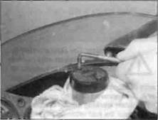
5.3 Slacken the two reservoir cover screws
5.4 Disconnect the brake light switch wiring connectors (arrowed)
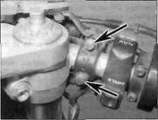
5.6 Note the alignment of the hose before removing the banjo bolt (arrowed)
| 5.7a Slacken the bracket bolt (arrowed)... |
2 Before disassembling the master cylinder,
read through the entire procedure and make
sure that you have obtain all new parts
required. Also, you will need some new DOT 4
brake fluid, some clean rags and internal
circlip pliers. Note: If the master cylinder is
just being displaced and not completely
removed or overhauled, do not disconnect the
brake hose or drain the reservoir.
Caution: Disassembly, overhaul and reassembly of the brake master cylinder must be done in a spotlessly clean work area to avoid contamination and possible failure of the brake hydraulic system components. To prevent damage to the paint from spilled brake fluid, always cover the fuel tank when working on the master cylinder.
Removal
3 Loosen, but do not remove, the screws holding the reservoir cover in place (see illustration). Access to the screws Is restricted by the windshield. If a short or angled screwdriver is not available, remove the fairing lo access the screws (see Chapter 8).
4 Disconnect the electrical connectors from the brake light switch (see illustration).
5 Remove the front brake lever (see Chapter 6).
6 Unscrew the brake hose banjo bolt and separate the hose from the master cylinder, noting its alignment (see illustration). Discard
the sealing washers as they must be renewed. Wrap the end of the hose in a clean rag and suspend it in an upright position or bend it down carefully and place the open end in a clean container. The objective is to prevent excessive loss of brake fluid, fluid spills and system contamination.

|
7 Slacken the bolt securing the reservoir bracket to the master cylinder (see illustration). Unscrew the master cylinder clamp bolts, then lift the master cylinder away from the handlebar (see illustration).
8 Remove the reservoir cover retaining screws and lift off the cover, the diaphragm plate and the rubber diaphragm. Drain the brake fluid from the reservoir into a suitable container. Remove the reservoir bracket bolt,
then release the clamp securing the reservoir hose to the union on the master cylinder and detach the hose. Wipe any remaining fluid out of the reservoir with a clean rag.
9 If required, remove the screw securing the
brake light switch to the bottom of the master
cylinder and remove the switch.
Overhaul
10 Carefully remove the dust boot from the end of the piston (see illustration).
11 Using circlip pliers, remove the circlip and slide out the piston assembly and the spring. noting how they fit (see illustration). Lay the parts out in the proper order to prevent confusion during reassembly (see illustration).
5.7b... then unscrew the clamp bolts
(arrowed) and remove the master cylinder
assembly


|

5.11a... then depress the piston and
remove the circlip using a pair of internal
circlip pliers
5.11b Lay out the internal parts as shown,
even if new parts are being used, to avoid
confusion on reassembly
7*8 Brakes, wheels and tyres


|
| 6.1a Remove the plug... |
12 Remove the fluid reservoir hose union rubber cap, then remove the circlip and detach the union from the master cylinder. Discard the O-ring as a new one must be used. Inspect the reservoir hose tor cracks or splits and renew if necessary.
13 Clean all parts with clean brake fluid or denatured alcohol. If compressed air is available, use it to dry the parts thoroughly (make sure it's filtered and unlubricated). Caution: Do not, under any circumstances, use a petroleum-based solvent to clean brake parts.
14 Check the master cylinder bore for corrosion, scratches, nicks and score marks. If the necessary measuring equipment is available, compare the dimensions of the piston and bore to those given in the Specifications Section of this Chapter. If damage or wear is evident, the master cylinder must be renewed. If the master cylinder is in poor condition, then the caliper(s) should be checked as well. Check that the fluid inlet and outlet ports in the master cylinder are clear.
15 The dust boot, circlip, piston, seal, primary cup and spring are Included in the new piston/seal kit. Use all of the new parts, regardless of the apparent condition of the old ones. If the seal and cup are not already on the piston, fit them according to the layout of the old piston assembly.
16 Install the new spring In the master cylinder so that its tapered end faces the piston.
17 Lubricate the new piston, seal and cup with clean brake fluid. Install the assembly into the master cylinder, making sure it is the correct way round (see illustration 5.11b). Make sure the lips on the cup do not turn inside out when they are slipped into the bore. Depress the piston and install the new circlip, making sure that it locates in the master cylinder groove (see illustration 5.11a).
18 Install the new rubber dust boot, making sure the lip is seated correctly in the piston groove (see illustration 5.10).
19 Fit a new O-ring onto the reservoir hose union, then press the union into the master cylinder and secure it with the circlip. Fit the rubber cap over the circlip.
20 Inspect the reservoir cover rubber diaphragm and renew it if it is damaged or deteriorated.
Installation
21 Install the brake light switch.
22 Attach the master cylinder to the handlebar and fit the clamp with its UP mark facing up, then tighten the bolts to the torque setting specified at the beginning of the Chapter (see illustration 5.7b).
23 Connect the brake hose to the master cylinder, using new sealing washers on each side of the union, and aligning the hose as noted on removal (see illustration 5.6). Tighten the banjo bolt to the torque setting specified at the beginning of this Chapter.
24 Install the brake lever (see Chapter 6).
25 Mount the reservoir onto the master cylinder and tighten its bolt securely (see illustration 5.7a). Connect the reservoir hose to the union and secure it with the clamp.
26 Connect the brake light switch wiring (see illustration 5.4).
27 Fill the fluid reservoir with new DOT 4 brake fluid as described in Daily (prs-ride) checks. Refer to Section 11 of this Chapter and bleed the air from the system.
28 Fit the rubber diaphragm, making sure it is correctly seated, the diaphragm plate and the cover onto the master cylinder reservoir (see illustration).
29 Check the operation of the front brake before riding the motorcycle.

6 Rear brake pads - renewal
| A |
Warning: The dust created by the brake system may contain asbestos, which is harmful to your health. Never blow it out with compressed air and don't inhale any of it. An approved filtering mask should be worn when working on the brakes.
1 Unscrew the pad retaining pin plug and the pad retaining pin, then unscrew the caliper mounting bolt (see illustrations).
2 Swing the caliper up at the back and slide out the pads (see illustration). Where fitted, remove the shims from the back of the pads, noting how they fit.
3 Inspect the surface of each pad for contamination and check that the friction material has not worn level with or beyond the wear grooves in the pad face or the cutouts in the pad edge (see illustration 2.2). If either pad is worn down to, or beyond, the wear limit, fouled with oi or grease, or heavily scored or damaged by dirt and debris, both pads must be renewed as a set. Note that it is not possible to degrease the friction material; if the pads are contaminated in any way they must be renewed.
4 If the pads are in good condition clean them carefully, using a fine wire brush which is completely free of oil and grease to remove all traces of road dirt and corrosion. Using a pointed instrument, clean out the grooves in the friction material and dig out any embedded particles of foreign matter. Any areas of glazing may be removed using emery cloth.
5 Check the condition of the brake disc (see Section 8).
6 Remove all traces ot corrosion trom the pad pin. Inspect the pin for signs of damage and renew it if necessary,
7 If new pads are being installed, push the pistons as far back into the caliper as possible. A good way of doing this is to insert one of the old pads between the outside of the disc and the piston, then push the caliper against the pad and disc using hand pressure
6.2 Swing the caliper up and remove the pads
Brakes, wheels and tyres 7*9
IT "21 1* £ 1ПWJ
Дата добавления: 2015-10-29; просмотров: 160 | Нарушение авторских прав
| <== предыдущая страница | | | следующая страница ==> |
| A The minimum disc thickness is marked on each disc | | | Push the caliper against the pad to create the extra room |