|
Читайте также: |
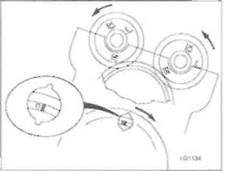
each mark upside down and on the inside of its respective gear, then no. 1 cylinder is at TDC on the compression stroke (see illustration). If the marks are not positioned as required for the cylinders being checked. turn the crankshaft through 360° (one complete turn).
7 With no. 4 cylinder at TDC on the
compression stroke, the following valves can
be checked:
a) No. 2, inlet
b) No. 3, exhaust
c) No. 4, inlet and exhaust
8 With no. 1 cylinder at TDC on the
compression stroke, the following valves can
be checked:
a) No. 1, inlet and exhaust
b) No. 2, exhaust
c) No. 3, inlet
9 Insert a feeler gauge of the same thickness
as the correct valve clearance (see
Specifications) between the cam base and
follower of each valve and check that it is a
firm sliding fit - you should feel a slight drag
when the you pull the gauge out (see
illustration). If not, use the feeler gauges to
obtain the exact clearance. Note: The inlet
and exhaust valve clearances are different.
Record the measured clearance on the chart.
10 Rotate the crankshaft through 360° and
measure the valve clearance of the remaining
valves using the method described in Step 9.
R models
11 Turn the engine until the line next to the
T mark on the alternator rotor aligns with the static timing mark, which is a notch in the inspection plug hole in the cover (see illustration 25.6a). Note: Turn the engine in the normal direction of rotation (clockwise). viewed from the right-hand end of the engine. Now, check the position of the camshaft gears - the 'IN' mark on the inlet camshaft gear and the 'EX' mark on the exhaust camshaft gear should be aligned with the cylinder head surface with each mark the correct way up and on the outside of its respective gear (see illustration). If the marks are not correctly positioned, turn the crankshaft through 360° (one complete turn).
12 With the engine in this position, the inlet valves for Nos. 2 and 4 cylinders can be checked.
13 Insert a feeler gauge of the same thickness as the correct valve clearance (see Specifications) between the cam base and follower of each valve and check that it is a firm sliding fit - you should feel a slight drag when the you pull the gauge out (see Illustration 25.9). If not, use the feeler gauges to obtain the exact clearance. Note: The inlet and exhaust valve clearances are different. Record the measured clearance on the chart.
14 With the specified valves measured, rotate the crankshaft clockwise through 180° (half a turn) until the line next to the 'O' mark on the alternator rotor aligns with the static timing mark, and so that the 'E' mark on the exhaust camshaft gear aligns with the cylinder
head surface, with the mark the correct way up and on the cutside of Its gear (see illustration). The exhaust valves for Nos. 1 and 3 cylinders can be checked.
15 Rotate the crankshaft clockwise through another 180° (half a turn) until the line next to the 'T mark on the rotor aligns with the static timing mark, and so that the 'IN' mark on the inlet camshaft gear and the 'EX' mark on the exhaust camshaft gear align with the cylinder head surface with each mark the wrong way up and on the inside of its respective gear (see illustration). ~he inlet valves for Nos. 1 and 3 cylinders can be checked.
16 Rotate the crankshaft clockwise through 180° (half a turn) until the line next to the 'О' mark on the alternator rotor aligns with the static timing mark, and so that the 'E' mark on the exhaust camshaft gear aligns with the cylinder head surface, with the mark the wrong way up anc on the inside of its gear (see illustration). The exhaust valves for Nos. 2 and 4 cylinders can be checked.
Adjustment
17 When all clearances have been measured and charted, identify whether the clearance on any valve falls outside that specified. If it does, the shim between the follower and the valve must be replaced with one of a thickness which will restore the correct clearance.
18 Shim replacement requires removal of the camshafts (see Chapter 2). There is no need
|

|

|
Дата добавления: 2015-10-29; просмотров: 201 | Нарушение авторских прав
| <== предыдущая страница | | | следующая страница ==> |
| B Turn the engine clockwise using a 14 mm socket on the alternator bolt | | | Fit new O-rings onto the plugs |