Читайте также:
|
bracket to create some freeplay
correctly installed at both ends - remove the fuel tank and air filter housing to access the carburettor end of the cable (see Chapter 4). If it is, then slacken the choke outer cable bracket screw on the carburettor and slide the cable further into the bracket, creating some freeplay (see illustration). Otherwise, renew the cable.

1 Remove the old spark plugs as described in Section 5 and install new ones.

|
17 Carburettors -
synchronisation
| A |
Warning: Petrol (gasoline) is extremely flammable, so take extra precautions when you work on any part of the fuel system. Don't smoke or allow open flames or bare light bulbs near the work area, and don't work in a garage where a natural gas-type appliance is present. If you spill any fuel on your skin, rinse it off immediately with soap and water. When you perform any kind of work on the fuel system, wear safety glasses and have a
fire extinguisher suitable for a Class В type fire (flammable liquids) on hand.
A Warning: Take great care not to burn your hand on the hot engine unit when accessing the gauge take-off points on the inlet manifolds. Do not allow exhaust gases to build up in the work area; either perform the check outside or use an exhaust gas extraction system.
1 Carburettor synchronisation is simply the process of adjusting the carburettors so they pass the same amount of fuel/air mixture to each cylinder. This is done by measuring the vacuum produced in each cylinder. Carburettors that are out of synchronisation will result in decreased fuel mileage, increased engine temperature, less than ideal throttle response and higher vibration levels. Before synchronising the carburettors, make sure the valve clearances are properly set.
2 To properly synchronise the carburettors, you will need a set of vacuum gauges or calibrated tubes (manometer) to indicate engine vacuum. The equipment used should be suitable for a four cylinder engine and come complete with the necessary adapters and hoses to fit the take-off points. Note: Because of the nature of the synchronisation procedure and the need for special instruments, most owners leave the task to a dealer.
3 Start the engine and let it run until it reaches
normal operating temperature, then shut it off.
Remove the fuel tank (see Chapter 4).
4 On J and К models, remove the blanking screws from the vacuum take-off points on the inlet manifolds (see illustration). Install the take-off adapters provided with the vacuum gauges (see illustration). Connect the vacuum gauge hoses to the adapters (see illustration). Make sure they are a good fit because any air leaks will result in false readings.
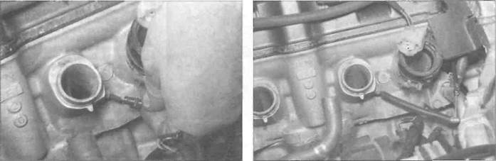
5 On L, N and R models, remove the air filter housing and displace the carburettors to access the vacuum take-off points (see Chapter 4) - there is no need to disconnect the cables, though it may be necessary to either detach the fuel hose or displace the fuel pump to provide enough slack. Remove the

|
17.4a Remove the blanking screws (arrowed) (cylinders 1 and 2 shown)...
17.4b... then fit the adapters.
17.4c... and attach the hoses
Lie Every 8000 miles (12,000 km) or 12 months
|
17.5a Remove the blanking caps...
17.5b... and attach the hoses

|
| Ш | m у L4X4X^X^1, |
| _I_ I Г| | |
| * |
17.8 Carburettor synchronisation set-up
17.9a Synchronisation screws (arrowed) - J and К models (air filter housing removed for clarity)
blanking caps from the vacuum take-off points on the inlet manifolds (see illustration). Connect the vacuum gauge hoses to the adapters or take-off points (see illustration). Make sure they are a good fit because any air leaks will result in false readings. Install the carburettors and air filter housing (see Chapter 4).
6 Arrange a temporary fuel supply, using a small temporary tank mounted above the level of the carburettors (see illustration 17.8). Connect the fuel supply hose from the tank to the inlet union on the in-line filter - do not connect it directly to the carburettors or you will by-pass the fuel pump.
7 Start the engine and make sure the idle speed is correct. If it isn't, adjust it (see Section 2). If the gauges are fitted with damping adjustment, set this so that the needle flutter Is just eliminated but so that they can still respond to small changes in pressure.
8 The vacuum readings for all of the cylinders should be the same, or at least within the tolerance listed in this Chapter's
Specifications (see illustration). If the vacuum readings vary, adjust as necessary.
9 The carburettors are adjusted by turning
the synchronising screws situated in-between
the carburettors, in the throttle linkage (see
illustrations). Note: Do not press down on
the screws whilst adjusting them, otherwise a
false reading will be obtained. First
synchronise the outer left carburettor (no. 1) to
the inner left carburettor (no. 2) using the left-
hand synchronising screw until the readings
are the same. Then synchronise the outer
right carburettor (no. 4) to the inner right
carburettor (no. 3) using the right-hand
synchronising screw. Finally synchronise the
left-hand carburettors (nos. 1 and 2) to the
right-hand carburettors (nos. 3 and 4) using
the centre synchronising screw.
10 When all the carburettors are synchronised, open and close the throttle quickly to settle the linkage, and recheck the gauge readings, readjusting if necessary.
11 When the adjustment is complete, recheck the vacuum readings, then adjust the
idle speed by turning the throttle stop screw (see Section 2) until the idle speed listed in this Chapter's Specifications is obtained. Stop the engine.
12 Remove the vacuum gauges and, where used, the adapters. Fit the blanking screws or caps onto the inlet manifolds.
13 Install the fuel tank (see Chapter 4).

17.9b Synchronisation screws (arrowed) -L, N and R models
Every 8000 miles (12,000 km) or 12 months w?
Дата добавления: 2015-10-29; просмотров: 168 | Нарушение авторских прав
| <== предыдущая страница | | | следующая страница ==> |
| Throttle cables | | | Rear suspension |