|
Читайте также: |
Engine, clutch and transmission 2*19

| Follower Shim Collets Spring retainer Valve spring Valve stem oil seal Spring seat Valve guide Valve |
 Disassembly
3 Before proceeding, arrange to label and store the valves along with their related components in such a way that they can be returned to their original locations without getting mixed up (see illustration). A good way to do this is to use the same container as the followers and shims are stored in (see Section 10), or to obtain a separate container which is divided Into sixteen compartments, and to label each compartment with the identity of the valve which will be stored in it (ie number of cylinder, inlet or exhaust side, inner or outer valve). Alternatively, labelled plastic bags will do just as well.
4 If not already done, clean all traces of old gasket material from the cylinder head. If a scraper is used, take care not to scratch or gouge the soft aluminium.
| Refer to Tools and | |
| HiNT | Workshop Tips for details of gasket removal methods. |
Q-©
| 12.3 Valve components |
5 Compress the valve spring on the first valve with a spring compressor, making sure it is correctly located onto each end of the valve assembly (see illustration). Do not compress the springs any more than is absolutely necessary. Remove the collets, using either needle-nose pliers, tweezers, a magnet or a screwdriver with a dab of grease on it (see illustration). Carefully release the valve spring compressor and remove the spring retainer, noting which way up it fits, the spring, the spring seat, and the valve from the head (see illustration 12.3). If the valve binds in the guide (won't pull through), push ft back into the head and deburr the area around the collet groove with a very fine file or whetstone (see illustration)
6 Repeat the procedure for the remaining valves. Remember to keep the parts for each valve together and separate from the other valves so they can be reinstalled in the same location.
7 Once the valves have beer removed and labelled, pull the valve stem seals off the top of the valve guides with pliers and
discard them (the old seals should never be reused).
8 Next, clean the cylinder head with solvent and dry it thoroughly. Compressed air will speed the drying process and ensure that all holes and recessed areas are clean.
9 Clean all of the valve springs, collets. retainers and spring seats with solvent and dry them thoroughly. Do the parts from one valve at a time so that no mixing of parts between valves occurs.
10 Scrape off any deposits that may have
formed on the valve, then use a motorised
wire brush to remove deposits from the valve
heads and stems. Again, make sure the valves
do not gel mixed up.
Inspection
11 Inspect the head very carefully for cracks
and other damage. If cracks are found, a new
head will be required. Check the cam bearing
surfaces for wear and evidence of seizure.
Check the camshafts tor wear as well (see Section 9).
12 Inspect the outer surfaces of the cam followers for evidence of scoring or other damage. If a follower is in poor condition, it is probable that the bore in which It works is also damaged. Check for clearance between the followers and their bores. Whilst no specifications are given, if slack is excessive, renew the followers. If the bores are seriously out-of-round or tapered, the cylinder head and the followers must be renewed.
13 Using a precision straight-edge and a feeler gauge set to the warpage limit listed in the specifications at the beginning of the Chapter, check the head gasket mating surface for warpage. Refer to Tools and Workshop Tips in the Reference section for details of how to use the straight-edge.
14 Examine the valve seats in the combustion chamber. If they are pitted, cracked or burned, the head will require work

|
12.5a Compressing the valve spring using a valve spring compressor
12.5b Remove the collets with needle-nose pliers, tweezers, a magnet or a screwdriver with a dab of grease on it
12.5c If the valve stem (2) won't pull
through the guide, deburr the area (1)
above the collet groove
2*20 Engine, clutch and transmission
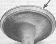
12.14 Measure the valve seat width with a
ruler (or for greater precision use a vernier
caliper)

|
T
12.15c Measure the small-hole gauge with a micrometer
beyond the scope of the home mechanic. Measure the valve seat width and compare it to this Chapter's Specifications (see illustration). If it exceeds the service limit, or if it varies around its circumference, valve overhaul is required. If available, use Prussian blue lo determine the extent of valve seat wear. Uniformly coat the seat with the Prussian blue, then install the valve and rotate it back and forth using a lapping tool. Remove the valve and check whether the ring of blue on the valve is uniform and continuous around the valve, and of the correct width as specified.
12.15a Measure the valve stem diameter with a micrometer
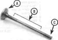
12.16 Check the valve face (A), stem (B)
and collet groove (C) for signs of wear and
damage
15 Measure the valve stem diameter (see illustration). Clean the valve guides to remove any carbon build-up. then measure the inside diameters of the guides (at both ends and the centre Of the guide) with a small-hole gauge and micrometer (see illustrations).The guides are measured at the ends and at the centre to determine if they are worn in a bell-mouth pattern (more wear at the ends). Subtract the stem diameter from the valve guide diameter to obtain the valve stem-to-guide clearance. If the stem-to-guide clearance is greater than listed in this Chapter's Specifications, the guides and
12.15b Insert a small-hole gauge into the
valve guide and expand it so there's a
slight drag when it's pulled out
valves will have to be renewed. If the valve stem or guide is worn beyond its limit, or if the guide is worn unevenly, it must be renewed.
16 Carefully inspect each valve face for cracks, pits and burned spots. Check the valve stem and the collet groove area for cracks (see illustration). Rotate the valve and check for any obvious indication that it is bent. Check the end of the stem for pitting and excessive wear. The presence of any of the above conditions indicates the need for valve servicing. The stem end can be ground down, provided that the amount of stem above the collet groove after grinding is sufficient.
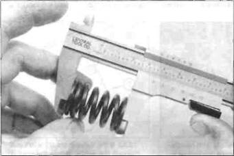
17 Check the end of each valve spring for wear and pitting. Measure the spring free length and compare it to that listed in the specifications (see illustration). If any spring is shorter than specified it has sagged and must be renewed. Also place the spring upright on a flat surface and check it for bend by placing a ruler against it (see illustration). If the bend in any spring is excessive, it must be renewed.
18 Check the spring retainers and collets for obvious wear and cracks. Any questionable parts should not be reused, as extensive damage will occur h the event of failure during engine operation.
| |
|

12.17a Measure the free length of the valve springs
12.17b Check the valve springs for squareness
Engine, clutch and transmission 2*21

|
|

|
Дата добавления: 2015-10-29; просмотров: 156 | Нарушение авторских прав
| <== предыдущая страница | | | следующая страница ==> |
| Make sure the gasket locates onto the dowels (A) and the UP mark (B) reads correctly | | | C ... then fit the spring retainer |