|
Читайте также: |
■ 3.1 Camera set up
■ 3.2 Sensor setting
■ 3.3 Relay setting
■ 3.4 Schedule setting
■ 3.5 System Setting
■ 3.6 Network setting
■ 3.7 User Setting
■ 3.8 System information & Product information
3.1 Camera set up
 |
3.1.1. Use
- Check box for setting the camera use.
3.1.2. Camera name
- Input the camera name for the camera control.
3.1.3. Pop up
- Camera channel pop up setting box when the motion or sensor activator is detected.
3.1.4. Secret (Channel hiding function)
- The user can set up the specific channel to open only to the registered user.
- The data is recorded as usual, but only registered user can see the data.
- To open the secret channel data to unregistered users, the user must remove the
secret set up.
3.1.5. Resolution
- The user can set up the recording resolution as below.
([ ] means resolution for PAL camera.)
- The resolution is different according to the model no. as below.
| CIF(LOW) 360 * 240 [360 * 288] | CIF(LOW) 320 * 240 |
| 2CIF(MIDDLE) 720 * 240 [720 * 288] | 2CIF(MIDDLE) 640 * 240 |
| VGA(HIGH) 720 * 480 [720 * 576] | VGA(HIGH) 640 * 480 |
3.1.6. Recording frames per second (fps)
- The user can set up the recording frames per second from 1 to max 30 frames for
each channel.
- The actually captured frame number through the selected camera is shown in the
second box.
It is different according to the model no. & resolution setting.
Ex) If the maximum recording speed is total 240 fps for 16 cameras, the number
in second box is max 15fps even though the user sets the recording fps as
30 fps in the first box.
3.1.7. Recording quality
- HIGH: It is the best image quality, but the data size is relatively big.
- MIDDLE: The image quality & data size are middle level.
- LOW: Relatively not good image quality compare to HIGH or MIDDLE, but the data
size is small.
- The user can set up the recording quality as each channel independently.
3.1.8. Audio channel and Camera channel connection
- If the user connects the audio channel to each camera channel,
 the user can hear the live audio data by choosing the
connected camera channel on the screen. The user can select
one camera channel among 16 channels and connect to one
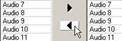 audio channel.
- Click the connection button after selecting camera & audio
channel.
- To delete the connection, click the delete button after selecting
camera channel.
3.1.9. Copy to all
- The user can apply current setting to all camera channels by pressing this button.
3.1.10. Copy on selected
- The user can apply current setting to the selected camera by pressing this button.
- The user can choose plural cameras by selecting the camera with pressing “Control
button (Ctrl)” on the keyboard.
3.2 Sensor setting
 |
3.2.1. Use
- The user can check whether each sensor is in use or not.
3.2.2. Sensor alarm type setting
- NC (Normal Close) / NO (Normal Open)
3.2.3. Sensor name edit box
- The user can input the sensor name here.
3.2.4. Camera channel setting for connection to a sensor
- The user can choose a camera channel among 16 channels and connect to the
selected sensor.
- Plural camera channels from 1 channel to 16 channels can be connected to each sensor.
- The user can see, revise, and edit the selected camera & sensor channel connection
status at the camera & sensor connection GRID box.
- The supported sensor number is different according to the model no.
3.2.5. Relay channel setting for connection to a sensor
- The user can choose a relay channel among 16 channels and connect to the selected
sensor.
- Plural relay channels from 1 channel to 16 channels can be connected to each sensor.
- The user can see, revise, and edit the selected relay & sensor channel connection status
at the relay & sensor connection GRID box.
- The supported sensor number is different according to the model no.
3.2.6. Copy to all
- The user can apply current setting to all sensor channels by pressing this button.
3.2.7. Copy on selected
- The user can apply current setting to the selected sensor by pressing this button.
- The user can choose plural cameras by selecting the camera with pressing
“Control button (Ctrl)” on the keyboard.
3.3 Relay setting
 |
3.3.1. Relay name edit box
- The user can input the relay name here.
3.3.2. Off method
- Relay operation mode setting.
- Manual: Relay is operated when an event (sensor or motion) is detected, and the user
can stop it manually.
The user can operate relay on/off manually by clicking each relay icon on “Sensor
& Relay status display” part of the main screen.
- Sensor: Relay works when the sensor alarm occurs, and stops the operation when the
sensor alarm is disappeared.
- Timer: The relay operation occurred by an event will be stopped after time set.
To use timer function, the user must set the minute & second at right side.
- Motion: When the user sets the recording schedule as motion detection recording mode,
the relay is operated according to the motion detection with this setting.
3.3.3. Camera channel setting for connection to a relay
- The user can choose a camera channel among 16 channels and connect to the selected
relay.
- Plural camera channels from 1 channel to 16 channels can be connected to each relay.
- The user can see, revise, and edit the selected camera & relay channel connection status
at the sensor & relay connection GRID box.
3.3.4. Copy to all
- The user can apply current setting to all relay channels by pressing this button.
3.3.5. Copy on selected
- The user can apply current setting to the selected relay channel by pressing this button.
- The user can choose plural cameras by selecting the camera with pressing “Control
button (Ctrl)” on the keyboard.
3.4 Schedule setting
- Recording schedule: Image recording mode schedule
- Relay schedule: Relay operation schedule according to motion detection, if the motion
detection recording mode is set.
- Notify schedule: Schedule for notifying an e-mail message to a remote client.
3.4.1. Recording schedule setting
- The user can set here the image recording modes, and recording schedule per time,
a day of the week, & channel.
 |
3.4.1.1. Continuous Recording: [ Mark: C, Color: Green ]
- If the user selects this mode, the image data of the connected camera is recorded
continuously & unconditionally as the resolution setting.
- Recording per a day of the week & time is available.
- To set this mode, choose “Continuous record” among the options.
- When the user drags the mouse in schedule setting box, the selected area turns to
green & is marked “C”.
3.4.1.2. Sensor recording: [ Mark: S, Color: Red ]
- If sensor alarm occurs, image data of the connected camera will be recorded.
- Recording per a day of the week & time is available.
- To set this mode, choose “Sensor record” among the options.
- When the user drags the mouse in schedule setting box, the selected area turns to
red & is marked “S”.
3.4.1.3. Motion detection recording: [ Mark: M, Color: Yellow ]
- Only the image data of a camera channel which detects any motion will be recorded.
- Recording per a day of the week & time is available.
- To set this mode, choose “Motion record” among the options.
- When the user drags the mouse in schedule setting box, the selected area turns to
green & is marked “M”.
3.4.1.4. Motion + Sensor recording: [Mark: M+S, Color: Orange color]
- If any sensor alarm or motion detection occurs, image data of the connected camera
channel will be recorded.
- Recording per a day of the week & time is available.
- To set this mode, choose “Motion + Sensor record” among the options.
- When the user drags the mouse in schedule setting box, the selected area turns to
orange color & is marked “M+S”.
3.4.1.5. None: [Mark: N ]
- No recording operation.
- Scheduling not to record per a day of the week & time is available.
- To set this mode, choose “None” among the options.
- When the user drags the mouse in schedule setting box, the selected area is marked
“N”.
3.4.1.6 Select all
- To schedule all as same mode, click the first square between Sun & O of the
schedule chart.
3.4.1.7 Select a line
- To schedule a line (horizontally or vertically) as same mode, click the time or a day of
the week.
3.4.1.8 Copy to all
- The user can apply current setting to all camera channels by pressing this button.
3.4.1.9 Copy on selected
- The user can apply current setting to the selected camera by pressing this button.
- The user can choose plural cameras by selecting the camera with pressing
“Control button (Ctrl)” on the keyboard.
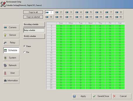
3.4.2. Relay schedule setting
- The user can set relay operation schedule as ‘unuse’ or ‘use’.
- Select the relay operation schedule per a day of the week & time.
- “Unuse” status is marked “X”, and “Use” status is marked “O”.
- Select all: To schedule all as same mode, choose the first square between Sun & O
of the schedule chart.
- Copy to all: The user can apply current setting to all camera channels by pressing
this button.
- Copy on selected:The user can apply current setting to the selected camera channel
by pressing this button.
- Select a line: To schedule a line (horizontally or vertically) as same mode, click the
time or a day of the week.
- The user can choose plural cameras by selecting the camera with pressing “Control
button (Ctrl)” on the keyboard.
 |
3.4.3. Notifying schedule setting
- Remote notifying schedule function e-mails the events such as sensor alarm, motion
detection, camera disconnection information to the registered remote client.
- The user can select plural options
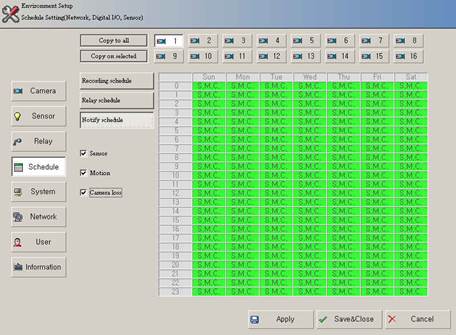 |
3.4.3.1. Notifying when sensor alarm (Sensor): [Mark: S]
- The user can set the schedule for notifying to a remote client when sensor alarm
occurs.
- The user can set the sensor alarm notifying schedule per a day of the week & time.
- To use this function, choose “Sensor” among the options.
- When the user drags the mouse in schedule setting box, the selected area is marked
“S”.
3.4.3.2. Notifying when motion detection: [Mark: M]
- The user can set the schedule for notifying to a remote client when any motion is
detected.
- The user can set the detected motion notifying schedule per a day of the week & time.
- To use this function, choose “Motion” among the options.
- When the user drags the mouse in schedule setting box, the selected area is marked
“M”.
3.4.3.3. Notifying when camera disconnection: [Mark: C]
- The user can set the schedule for notifying to a remote client when camera
disconnection occurs.
- The user can set the camera disconnection notifying schedule per a day of the week
& time.
- To use this function, choose “Camera Loss” among the options.
- When the user drags the mouse in schedule setting box, the selected area is marked
“C”.
3.4.3.4. No remote notifying: [Mark: N]
- If the user does not need the remote notifying function, do not choose any notifying
schedule.
- When the user drags the mouse in schedule setting box, the selected area is marked
“N”.
- The event occurred in the scheduled day of the week & time set as “N” is not
notified.
3.4.3.5. Plural conditions setting for event notifying [Mark: S+M,S+C, M+C, S+M+C]
- The user can schedule plural conditions for event notifying.
- To use this function, choose the options the user wants to set.
(Plural selections available)
- This function will be operated when any event under the scheduled conditions occurs.
- Plural conditions for remote notifying are as below.
Sensor + Motion: Mark (S,M)
Sensor + Camera loss: Mark (S,C)
Motion + Camera loss: Mark (M,C)
Sensor + Motion + Camera loss: Motion (S,M,C)
3.4.3.6 Select all
- To schedule all as same mode, click the first square between Sun & O of the
schedule chart.
3.4.3.7 Select a line
- To schedule a line (horizontally or vertically) as same mode, click the time or a day of
the week.
3.4.3.8. Copy to all
- The user can apply current setting to all camera channels by pressing this button.
3.4.3.9. Copy on selected
- The user can apply current setting to the selected camera channel by pressing this
button.
.
3.5 System Setting
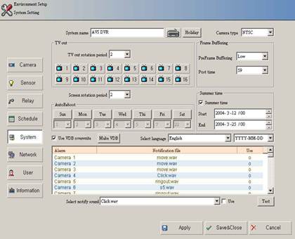
3.5.1. System name
- Input the distinguishable DVR name.
3.5.2 Holiday setting
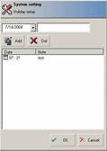 |
- The user can set a specific date as “holiday” to use
holiday function by pressing the holiday button.
- The recording mode of “holiday” is following the
recording mode of “Sunday” set in the Schedule setting
part.
3.5.3. Camera type setting
- NTSC or PAL type is available.
3.5.4. TV out setting
- TV out rotation period: The user can choose among 2,5,10,15,20,30 seconds.
- Select the camera channel to set TV out rotation.
3.5.5. Screen rotation period setting
- The user can set the rotation period here.
- Screen rotation period: The user can choose among 2,5,10,15,20,30 seconds.
- Channel not in use is excluded from the rotation.
3.5.6. Use VDB overwrite.
- This setting is for overwriting from the first index point if all VDB spaces are full.
3.5.7. Auto Reboot setting
- Periodic auto rebooting is required to operate the system stably.
- Choose a day of the week to set auto rebooting.
- Choose time to set auto rebooting.
- The user can select specific time of a day or plural days of every week.
- The system is automatically rebooted at the assigned time & day of the week.
3.5.8. Make VDB
- This setting is for adding new VDBs.
- VDB producing utility is displayed when the user clicks this button.
 |
3.5.8.1. Create VDB
- The user can select the drive to create VDB in the Drive info box.
(VDB can not be created in “C” drive because it is space for OS.)
 - Input the VDB no. to create.
(Select UP/DOWN BUTTON)
- “Creatable VDB” number is inputted in “VDB to make” when the user
 presses
- The creating procedure is displayed when the user inputs the no. and presses the
 button.
- “Creatable VDB” means the maximum number of VDB that can be created &
“Allocated VDB” means the number of created VDB until now.
- When creating VDB is completed, click “OK” button.
If the user creates VDBs through the “Environment set up”, the screen goes back to
pre-screen.
If the user tries the first operation of the DVR & the “VDB Utility” page floats up, VDB
creation in this page must be done first.
In this case the “OK” button leads the user to the main screen of the DVR.
3.5.9. Frame Buffering setting
- Frame buffering means setting recording frame number of before and after of the event
when a motion or sensor occurs.
- The user can select Pre-Frame Buffering option among LOW, MIDDLE, HIGH level
sizes.
- The user can set Post time option from 0 to 59 seconds.
3.5.10. Summer time setting
- Summer time is an artificial time system to advance 1 hour ahead of usual time in
summer.
Many countries practice summer-time to adjust life time to the extended sunshine duration.
This DVR system has summer time setting function for the time change in such countries in
summer.
- To set this function, click the small box beside the “summer time”.
- Set the start & end date, month, time of summer-time period.
- The last one hour is not existed before the starting time and an hour is repeated 2
times at the end of summer-time period. The recorded data in summer-time period is
marked “D” in Time Table.
3.5.11. Select language
- The language pack of this DVR can be changed.
- The user must select ‘yes’ when the system asks rebooting after pressing save &
close button.
3.5.12. Date display type setting
- The user can change date & time display type of this DVR.
- Display type
Year-Month-Date: YYYY-MM-DD
Month-Date-Year: MM-DD-YYYY
Date-Month-Year: DD-MM-YYYY
3.5.13. Select notifying sound
The user can select alarm sounds for notifying Camera loss, Motion detection, &
Sensor alarm event.
When any event mentioned above occurs, the set sound for each event rings.
- To set this function, click ‘use’ beside ‘Test’ on the screen after selecting the
camera, motion, sensor no. in the Alarm- Notification- Use box.
- Alarm sound type
Camera loss (ch 1 ~ ch 16), Motion detection event (ch 1 ~ ch 16),
Sensor alarm event (ch 1 ~ ch 16)
(The supported sensor number is different according to the model no)
3.6 Network setting
This setting is for network connection from remote client.
To correspond with remote client, click “Use network”.

3.6.1. Network use setting: Click “Use” check box.
3.6.2. Network type setting
3.6.2.1. LAN
- Leased internet line / ADSL / VDSL
- High speed data processing of video, audio, sensor, relay, and camera information is
available.
3.6.2.2. ISDN / Modem
- Low speed data processing is available, so video, audio, sensor, relay, and camera
information is handled within limited speed.
3.6.3. E-mail notification
3.6.3.1. Details
- If the user sets this function, sensor alarm, motion detection & Camera loss
information is sent to the assigned e-mail address.
- E-mail notification including image is sent when a motion is detected or sensor is
activated.
- To use this function, the user must set DNS server address in the “TCP/IP setting”.
- The user does not need to input mail server. (SMTP Relay system)
3.6.3.2. Setting
- To set this function, click “Email notification”.
- Position information input: Describe shortly the location where the DVR system is
installed.
3.6.4. Remote notification setting
- This function is for transmitting the DVR system status information & event data to a
specific client PC, while it is being connected to the DVR through the RS program
(Remote Surveillance program).
- To set this function, click the check box “use”.
- Then input the IP address of the client site.
- The user can add sites by pressing “ADD” button.
- The user can delete sites by pressing “DEL” button.
- Maximum 10 client PCs can be registered.
3.6.5 Etc
3.6.5.1. Grant anonymous connection.
- The GUEST mode provides Basic surveillance functions. (Video monitoring & search)
- The user can set the limitation of the anonymous user’s connection by each
channel.
- The anonymous user can see & playback the data of the allowed channels only,
through the network.
3.6.5.2. TCP/IP setting
- The user can set TCP/IP network setting here without system off.
3.6.5.3. Port Info
- The user can change the network port information.
- When changing port info, it should be changed in Network client side, too.
3.6.5.4. Use Web
- The user can select to allow remote access to the live & recorded image of the DVR
system through internet browser (Internet Explorer) or not.
3.6.5.4 Web Port
- This is port for Web application. Web is using the 80 port basically. If user want to
another port, user should enter the IP address and port No in the address bar.
(Refer to Web Monitoring Manual)
3.7 User Setting
- This part is for setting the user’s level related to the DVR system control.
- The available functions by each user’s level can be set here.
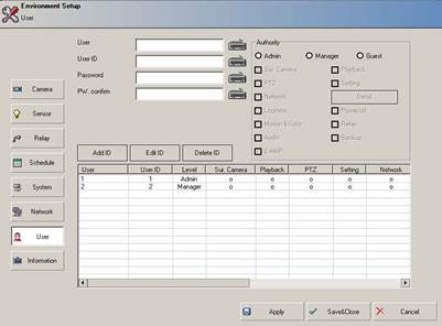 |
3.7.1. User’s authority setting.
- ADMIN: The highest user level. Basically the user in this level can operate all functions
and add, delete, and edit the same & lower level user.
- MANAGER: The user level under ADMIN. Basically the user in this level can operate all
functions and add, delete, and edit the same & lower level user.
But the manager level user can not add, delete, and edit the ADMIN level user.
- GUEST: The lowest user level. Basically the user in this level can operate only image
surveillance, search, and network connection.
- Factory Default: This user level is for the first log-in of the DVR system.
3.7.2. The selectable functions for each level user.
- Surveillance Camera - Playback
- PTZ control - Environment Setting
- Network - System power OFF
- Log viewer - Relay control
- Motion & Color setting - Back up
- Audio control - E-map use
3.7.3. Add user
- Input the user’s name.
- Input the user’s ID.(8 letters or under, including alphabet or number)
- Input the user’s password. (8 letters or under, including alphabet or number)
- Re-input the user’s password.
- Set the user’s level. (Authority)
- Select the available functions for the new user.
- The new user can be registered by pressing ‘Add ID’ button.
- The user’s information will be displayed in the user list box after adding a new user.
New user can be registered when the setting user is in same level or higher level.
For example, if the setting user is in manager level, the user can not add ADMIN level user
3.7.4. Delete user
- Select the user information to delete among the registered users in the user list box.
- Click the “Delete ID” button.
- The selected ID will be deleted from the list.
User’s ID can be deleted when the setting user is in same level or higher level.
For example, if the setting user is in manager level, the user can not delete ADMIN level
user.
3.7.5. Edit ID
- Select the user information to edit among the registered users in the user list box.
- The selected user information will be displayed at the upper side of the user list box as
edit mode.
- Revise the information to edit.
- Click the “Edit ID” button after completing correction.
- The corrected information will be displayed in the user list box after the edit procedure.
User’s information can be revised when the setting user is in same level or higher level.
For example, if the setting user is in manager level, the user can not revise ADMIN level
user’s information.
3.7.6. Detail (Detailed authority setting for using Network functions)
- The user can set the limitation of the remote client’s authority for operating the network
functions like two-way audio communication, monitoring, & relay control through network.
- The default setting is set as “all checked” and that means the above three functions & all
channels are allowed to the selected user.
- If the user presses the “Detail” button, the below setting box will be shown.
 |
3.7.6.1 Two-way audio communication
- The user can allow the authority for using two-way audio communication to the
selected user by checking the check box.
3.7.6.2 Monitoring
- The user can allow the authority for monitoring or playback the data of the checked
channels to the selected user. The selected user can see and playback the data
of the checked channels only, through network.
3.7.6.3 Relay control
- The user can allow the authority for controlling the checked relays to the selected
user. The selected user can control the checked relays only, through network.
- “Relay” function in “Authority” part should be checked before this setting, to
allow the relay control function to the selected user.
3.8 System Information & Product Information
The user can see the setting information of the DVR system & network, system options,
and version here synthetically.
 |
3.8.1. Product Information
- Product version information.: ex) 0.10.001.040410 - Board number.
- Camera channel number - Audio channel number
- Sensor channel number - Relay channel number
3.8.2. Network Information
- The user can see here all network environment setting of this system.
- Host name, Domain name, DNS server, TCP/IP setting, Network adapter etc.
3.8.3. VDB information
- The user can check the created VDB file information of this system like directory route that
the VDB is created through and starting & ending time of recorded data in the VDB data
file.
3.8.4. System information
- Options of this DVR system can be checked.
- OS type - Computer name
- RAM quantity - CPU INFO.
- Available Memory - RAM using rate.
- DIRECTX version information
 4
4
Chapter
Дата добавления: 2015-08-27; просмотров: 74 | Нарушение авторских прав
| <== предыдущая страница | | | следующая страница ==> |
| User log-in | | | PTZ Control |