|
Читайте также: |
The main purpose to initiate layout on is to define overall dimensions of the part, allowing to assess possibilities to allocate reduction unit within given mounting space. Overall dimensions are measured as length L, width B and height H (Figure 4) in approximation.
The layout is performed in the following sequence:
1. Axle to axle space  is measured and axles of both input and output shafts are drawn. For this reason it’s 1 mm paper should be used. Scale of the drawing to be 1:1.
2. Then the profiles of the wheels are drawn. Dash-and-dot lines are made corresponding to pitch surface of pinion diameter  and wheel diameter
  .
.
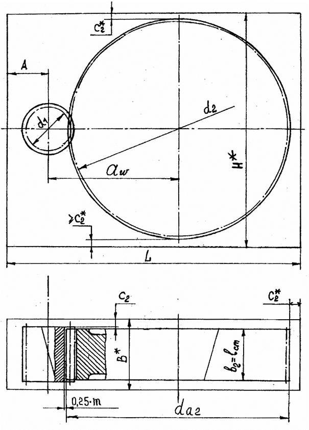
Figure 4. Single step reduction unit Layout beginning.
Overall dimensions of toothed gears are drawn: the flat end surfaces of the wheels are displayed, the distances between them assumed equal to  , then flat end surfaces of pinion are shown with spacing between them as equal to
  ; then the surfaces of the wheel tips are drawn, which diameter to be equal to
  for the wheel and
  for the pinion. In coupling one of tip surface lines for instance of the pinion is drawn in dash-and-dot lines; teeth pit surfaces are drawn, ensuring spacing between teeth surfaces equal to
  mm in coupling.
3. Upon tooth rim width ratio being as  and
and  the length of the wheel nave can be taken as equal to wheel rim width .
4. The gaps between running wheels and inner surfaces of housing walls are set as being as follows for example:
- the gap between the surface of the wheel tooth tips and inner housing wall of the reduction unit
 ;
;
- the gap between flat end of the wheel and inner housing wall of the reduction unit
 ;
;
- the gap between input shaft axle and side surface of inner housing wall of the reduction unit can be set preliminary equal to
 ,
,
upon further development of the design the position of side walls can be defined more precisely.
5. The overall dimensions L,B* and H are then defined.
Дата добавления: 2015-10-31; просмотров: 86 | Нарушение авторских прав
| <== предыдущая страница | | | следующая страница ==> |
| Designed calculation of helical gear | | | Design-basis calculation of the shafts |