|
Читайте также: |
| | |
general check
|
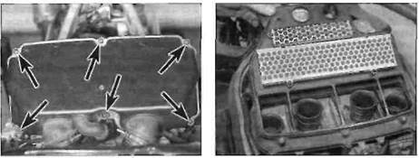
8.3b Air filter cover screws (arrowed) -L, N and R models
8.3c Removing the element ■ J and К models
Tyres
1 Check the tyre condition and tread depth
thoroughly - see Daily (pre-ride) checks.
Wheels
2 Cast wheels are virtually maintenance free,
but they should be kept clean and checked
periodically for cracks and other damage.
Also check the wheel runout and alignment
(see Chapter 7). Never attempt to repair
damaged cast wheels; they must be renewed
if damaged. Check the valve rubber for signs
of damage or deterioration and have it
renewed if necessary. Also, make sure the
valve stem cap is in place and tight.
|
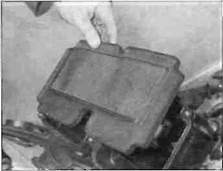
8.3d Removing the element-L, N and R models
| /q^ | , й |
| '^0 | M |
| % | •^^H |
| ■ |
8.4 Direct the air from the inside out
8.7 On L, N and R models, locate the inlet tabs on the air duct lugs (arrowed)
1.12 Every 4000 miles (6000 km) or 6 months
|
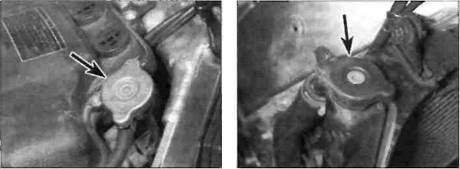
10.6a Pressure cap (arrowed) -J and К models
10 Cooling system - check
I I
| A |
Warning: The engine must be cool before beginning this procedure.
1 Check the coolant level (see Daily (pre-ride) checks).
2 Remove the lower fairing (see Chapter 8). The entire cooling system should be checked for evidence of leakage. Examine each rubber coolant hose along its entire length. Look for cracks, abrasions and other damage. Squeeze each hose at various points. They should feel firm, yet pliable, and return to their original shape when released. If they are dried out or hard, renew them.
3 Check for evidence of leaks at each cooling system joint. Tighten the hose clips carefully to prevent future leaks.
4 Check the radiator for leaks and other damage. Leaks in the radiator leave tell-tale scale deposits or coolant stains on the outside nf the core helnw the leak. If leaks are noted, remove the radiator (see Chapter 3) and have it repaired by a specialist. Caution: Do not use a liquid leak stopping compound to try to repair leaks.
5 Check the radiator fins for mud, dirt and insects, which may impede the flow of air through the radiator. If the fins are dirty, remove the radiator (see Chapter 3) and clean it using water or low pressure compressed air directed through the fins from the backside. If the fins
10.6b Pressure cap (arrowed) - L, N and R models
are bent or distorted, straighten them carefully with a screwdriver. If the air flow is restricted by bent or damaged fins over more than 30% of the radiator's surface area, renew the radiator.
6 On J and К models, remove the fuel tank (see Chapter 4). On L, N, and R models, remove the right-hand fairing side panel (if not already done), and, if required for improved access, the trim panel covering the pressure cap (see Chapter 8). Remove the pressure cap from the radiator filler neck by turning it anti-clockwise until it reaches a stop (see illustrations). If you hear a hissing sound (indicating there is still pressure in the system), wait until it stops. Now press down on the cap and continue turning the cap until it can be removed. Check the condition of the coolant in the system. If it is rust-coloured or if accumulations of scale are visible, drain, flush and refill the system with new coolant (See Section 27). Check the cap seal for cracks and other damage. If in doubt about the pressure cap's condition, have it tested by a dealer or renew it. Install the cap by turning it clockwise until it reaches the first stop then push down on the cap and continue turning until it nan turn no further.
7 Check the antifreeze content of the coolant with an antifreeze hydrometer. Sometimes coolant looks like it's in good condition, but might be too weak to offer adequate protection. If the hydrometer indicates a weak mixture, drain, flush and refill the system (see Section 27).
8 Start the engine and let it reach normal operating temperature, then check for leaks again. As the coolant temperature increases, the fan should come on automatically and the
temperature should begin to drop. If it does not, refer to Chapter 3 and check the fan and fan circuit carefully.
9 If the coolant level is consistently low. and no evidence of leaks can be found, have the entire system pressure checked by a dealer.
11 Brake system - check %
1 A routine general check of the brake system will ensure that any problems are discovered and remedied before the rider's safety is jeopardised.
2 Check the brake lever and pedal for loose connections, improper or rough action, excessive play, bends, and other damage. Renew any damaged parts (see Chapter 7).
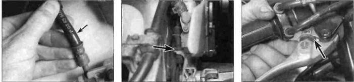
3 Make sure all brake fasteners are tight. Check the brake pads for wear (see Section 3) and make sure the fluid level in the reservoirs is correct (see Daily (pre-ride) checks). Look for leaks at the hose connections and check (or cracks in the hoses (see illustration). It the lever or pedal is soongy, bleed the brakes (see Chapter 7).
4 Make sure the brake light operates when the front brake lever is pulled in. The front brake light switch, mounted on the underside of the master cylinder, is not adjustable. If it fails to operate properly, check it (see Chapter 9).
5 Make sure the brake light is activated just before the rear brake takes effect. If adjustment is necessary, hold the switch and turn the adjuster ring on the switch body until the brake light Is activated when required (see illustration). The switch is mounted on the inside of the rider's right-hand footrest bracket, just ahead of the master cylinder. If the brake light comes on too late, turn the ring clockwise. If the brake light comes on too soon or is permanently on. turn the ring anti-clockwise. If the switch doesn't operate the brake light, check it (see Chapter 9).
6 The front brake lever has a span adjuster which alters the distance of the lever from the handlebar (see illustration). Each setting is identified by a notch in the adjuster which aligns with the arrow on the lever. Pull the lever away from the handlebar and turn the adjuster ring until the setting which best suits the rider is obtained, "here are two settings.
|
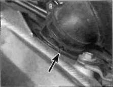
11.3 Flex the brake hoses and check for cracks, bulges and leaking fluid
Дата добавления: 2015-10-29; просмотров: 184 | Нарушение авторских прав
| <== предыдущая страница | | | следующая страница ==> |
| Tighten the drain plug securely | | | Front brake lever span adjuster (arrowed) |