|
Читайте также: |
Heat pipe heat exchanger
A heat pipe is a sealed self-contained, liquid evaporating condensing system, usually shaped like a cylinder. Heat is transferred from the hot incoming gas to the evaporator section of the heat pipe. The local vapour pressure increases and evaporated fluid flows along the pipe to the condenser section. The vapour pressure is lower here, so the liquid condenses and the heat is released to the cold gas. The liquid then returns to the evaporator by a combination of capillary action and gravity (figure 1).

Fig.1
Energy performance
Applications / Advantages / Disadvantages
· Works in range up to about 300°C.
· Rapid heat transfer ensures uniform heat delivery.
Rotary regenerator (heat wheel)
The rotary regenerator, or heat wheel, is a gas-to-gas rotating heat exchange that transfers energy from an exhaust to a supply gas. The heat wheel spans two adjacent ducts. One of the ducts carries the exhaust gas; the other carries the incoming gas, which is to be heated, against the current (figure 2). Normally, inter-stream leakage must be allowed, though this can be significantly reduced in some designs.

Fig.2
Energy performance
Applications / Advantages / Disadvantages
If exhaust and supply flow rates are equal (or in other favourable circumstances), 65% or more of available heat can be recovered.
Can be cost-effective in furnaces, ovens, printing machinery, paper drying and HVAC systems.
More compact, lighter, and has higher temperatures than the comparable recuperator, so lower gas exit temperatures are possible.
Run-around coil
A run-around coil system is an indirect heat exchanger network between two fluid streams that are some distance apart. It is an effective way of connecting pipe work carrying a liquid, usually water, water/glycol or a high temperature fluid. The heat exchangers used in the system are usually extended surface/finned tube coils, fitted into the ductwork, and joined by pipe work with a circulating pump.
Energy performance
Applications / Advantages / Disadvantages
· Recover mostly sensible heat with efficiencies of 40%–60%, and 70% in some designs.
· Applicable to low temperature (50°C–150°C) waste heat recovery problems, but not HVAC installations.
· Used in drying processes, paint spraying or drying ovens (like the heat pipe or the regenerator).
· No re-routing of duct work is required.
· There is no risk of cross contamination since an intermediate fluid is used in a sealed system.
Recuperator
In a gas-to-gas recuperative heat exchange system, heat from a hot flue or exhaust gas stream is transferred to an incoming air or process gas stream. Recuperators are usually used to transfer heat from exhaust gases to combustion air. Radiation type recuperators recover the heat from hot gases via concentric tubes. The waste gas flows through the central tube, while the air to be preheated flows through the surrounding annulus.
A simple convective type recuperator is constructed from bundles of tubes which the air to be preheated passes through. The hot gases pass over the tubes in either a single or a multi-pass design (figure 3).

Fig.3
The design and construction materials are affected by:
· the temperature of the gas (light metal construction usually limits the temperature to about 250°C; whereas the use of alloys or ceramics allows temperatures up to 1000°C);
· the corrosion/erosion aspects of the gas type; and
· how clean the gas is.
Energy performance
Applications / Advantages / Disadvantages
Efficiency of heat recovery varies:
· radiation type recuperators (30%);
· convective recuperative systems (50%–60%);
· advanced designs, eg. self-recuperative burners, up to70%.
· Steel industry (furnaces, soaking pits, chimneys and flues).
· Low temperature applications (textiles, food, brewing, pulp and paper).
· High temperature applications (flue gases from kilns, metal processing furnaces, glass melting furnaces, etc.)
Can handle very dirty, abrasive dust-laden gases.
Shell and tube
The shell and tube heat exchanger is the most common type used in the process, chemical and oil industries. It can be designed to operate over the full range of temperatures and pressures found in these industries. This type of heat exchanger usually has an arrangement of tubes, containing two liquids moving in counter current, surrounded by a cylindrical shell (figure 4). This type is also used to exchange heat between hot gases and liquids with high temperature differences, for example waste heat boiler designs. Some units feature self-cleaning via automatic flow reversal.
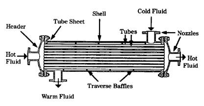
Fig.4
Energy performance
Applications / Advantages / Disadvantages
· Efficiency as high as 90%, depending on the application.
· Meets most operating conditions and temperatures up to 500°C.
· Cost efficiency achieved by increasing the number of passes.
Used in all of the process industries, to recover heat from hot liquors and effluent process streams, hot waste gas streams, etc.
Compact arrangement and high heat transfer area achieved in a small envelope.
Can be prone to fowling
Spiral heat exchanger
In the spiral heat exchanger the hot fluid enters at the centre of the unit and flows from the inside outwards. By contrast, the cold fluid enters at the periphery and flows towards the centre. Because the cold fluid flows around the outside of the unit the design is effectively self-insulating.

Fig.5
Energy performance
Applications / Advantages / Disadvantages
· Temperature range up to 400°C.
· Very high heat transfer efficiency.
· Similar to plate heat exchanger in limited pressure range (up to 18 bar).
· Not competitive where the PHE is suitable.
· Limited in terms of maximum working pressure.
· High fouling resistance and self-cleaning ability, unlike the PHE.
Plate heat exchanger
The plate heat exchanger (PHE) provides one of the most compact and cost effective solutions to heat exchange problems involving liquid to liquid heat exchange. Each plate is separated by a gasket and the streams flow through alternate passages. Heat exchange surface areas of over 2500m2 can be provided and liquid flow rates can range up to 17m3/sec. The geometric design of the plate surfaces induces turbulent flow, and this leads to high heat transfer rates. It is, however, limited in terms of its maximum working temperature and pressure.
A variety of standard designs of modular construction is available.
Type of plate heat exchanger
1. Construction
2. Comments
3. Plain form
A series of separate, parallel plates forms thin passages through which the heating and cooling fluids flow.
· Temperature range: -25°C – +170°C, (special designs up to 200°C).
· Easy to clean replace parts and increase capacity.
· Liquid-to-liquid systems recover up to 80-90% of the available heat.
· Widely used in the brewing, dairy and chemical process industries; in regenerative recovery, and as a condenser for product heating.
· Welded plate heat exchanger
· Plates are mounted within a shell so the cost will be more than the plain form for the same duty.
· Can operate at high temperatures (over 400°C).
· Has a large heat exchange area and can withstand high pressures (similar to shell and tube heat exchanger).
· Limited by cleaning problems (chemical methods are usually necessary) and the differential pressure between the fluids.
· Lamanella heat exchanger
· Two thin dimpled metal strips are welded together at the edges, forming long, straight channels or lamella.
· Can operate at high temperatures (up to 500°C).
· Flow channels mean low pressure drop, and ability to handle suspensions, slurries and fibrous materials.
· High thermal efficiency.
· Suitable for gas-to-gas duty.
Heat pump
Heat pumps extract energy from low temperature heat sources and upgrade it to higher and more effective temperatures. Heat pumps are used in two major areas in industrial situations: the steam recompression cycle (see next section) and the closed cycle heat pump (best suited to convective drying processes).
The heat pump process can be summarised as follows:
· The humid exhaust gas from a drying process is cooled below the dew point in the evaporator section of the heat pump.
· The energy in the latent heat of the vapour is given up to the working fluid of the heat pump.
· The fluid of the system is compressed, which raises its pressure and its temperature.
· This fluid vapour is condensed, giving back its latent heat of evaporation to the original process gas.
· The existing gas, now dry, will be upgraded to the higher working temperature of the drying process plant (figure 6).
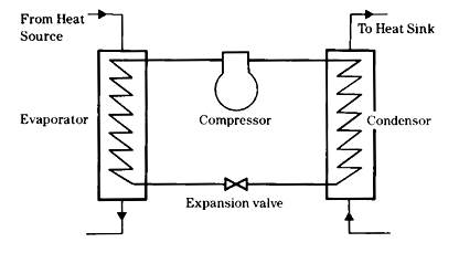
Fig.6
The efficiency, or coefficient of performance (COP), of the heat pump is usually expressed as the ratio of useful heat output to the amount of energy used to drive the compressor. The COP is maximised by keeping the temperature difference between the source and the output as small as possible. Heat pumps are designed to operate up to a maximum specified temperature that is characteristic of the working fluid.
Energy performance
Applications / Advantages / Disadvantages
· Heat drawn from warm, moist exhaust can achieve COPs of 5 or 6.
· Maximum operating temperature can vary (40°C, 60°C or 100°C, depending on choice of working fluid).
Timber and wood products; ceramics and pottery; textiles; brick manufacture; and food products.
Reclaims heat at ambient temperatures.
Process steam recompression
Steam is used in many industries as a heating medium to evaporate, distil and dry liquids. It is possible to recover the waste heat that is usually rejected by these processes by using a steam recompression system. This system, known as mechanical vapour recompression (MVR), is a heat pump in which the working fluid, steam or vapour produced is used to heat the process. The vapour produced is compressed, raising its pressure and temperature, and then passed through the heat exchanger where it gives up its latent heat to the process (figure 7).

Fig.7
Energy performance
Applications / Advantages / Disadvantages
· Specific energy consumption as low as 16 kWh/tonne of water evaporated.
· Can provide a very high COP with significantly reduced steam demand.
· Temperature range of 60°-140°C is possible.
Evaporation, distillation and drying in distilleries, dairies, brewing, chemical and pharmaceutical industries.
Lower operating costs than would be achieved with a conventional evaporator.
Дата добавления: 2015-08-03; просмотров: 51 | Нарушение авторских прав
| <== предыдущая страница | | | следующая страница ==> |
| Introduction | | | Heat recovery ventilation |